


14 Chapter 2 600r server description
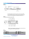
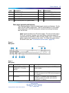
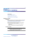
Figure 1
Front panel
The following diagram shows the front panel controls and status LEDs.
For more information about the front panel controls and status LEDs, see
CallPilot 600r Server Maintenance and Diagnostics (NN44200-703.)
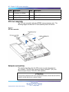
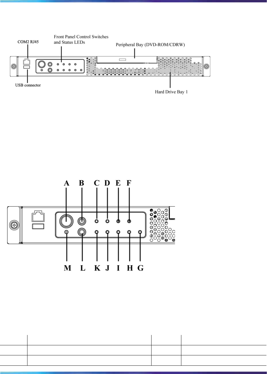
Figure 2
Front panel control switches and status LEDs
Note: The faults described in the following table are hardware faults and
are independent of CallPilot application faults.
Table 1
Front panel
Label Description Label Description
A Power button M NMI button (not used)
B Reset button L ID button
Nortel CallPilot
600r Server Hardware Installation
NN44200-307 01.03 Standard
5.0 14 May 2008
Copyright © 2007-2008, Nortel Networks
.