


40 Chapter 5 Connecting the server to power
AC requirements as specified on the label of the power supply cover.
To access the power supply cover, remove the server cover. For more
information about how to remove the server cover, see "To remove the
server cover" (page 24).
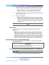
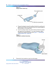
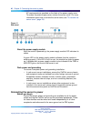
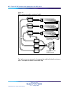
Figure 12
Rear panel
About the power supply module
After the server is powered up, the power supply module LED indicates its
status.
A green LED on the power supply module indicates that the module is
working properly. If the LED is not lit or red, the module has failed to power
up. A problem with a power supply module is also indicated if the PWR or
MJR LED light on the front of the server is red.
Rack power and grounding
To ensure a complete power and grounding installation:
•
In rack-mount server installations, ensure the CallPilot server chassis
and equipment racks are isolated from other foreign sources of ground.
Acceptable isolation methods include: isolation pads, grommeted
washers, chassis side-rail strips, and non-conducting washers (not
included.)
•
In rack-mount server installations where other equipment is also
installed in the same rack, ensure that all equipment derives ground
from the same service panel as CallPilot and the switch.
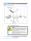
Connecting the server to power
Before you begin
Ensure that proper power and grounding are available for all the power
outlets serving the CallPilot server and its associated peripherals. Power
for these devices must be wired and fused independently of all other
receptacles and referenced to the same ground as the PBX system.
Nortel CallPilot
600r Server Hardware Installation
NN44200-307 01.03 Standard
5.0 14 May 2008
Copyright © 2007-2008, Nortel Networks
.