


Alteon Web Switch Hardware Installation Guide
Chapter 2: Installing the Switch Hardware
19
212779-A, December 2001
Connecting Power
The following instructions are for AC powered and DC powered Alteon switches.
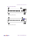
AC Power
1. Connect the power cord to the Web switch. Verify that the power switch is in the off
position.
2. Plug the switch cord into a properly fused AC outlet.
3. Power On (|) the switch.
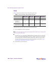
DC Power
The wire terminal block on the back of the chassis is for connecting the lead wires for standard
DC power.
Follow the instructions below to connect the switch to a -48 to -60 VDC SELV source only, in
compliance with National Electrical Code (NEC) articles 110-26 and 110-27.
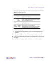
1. Be sure that DC power is turned off at the source.
2. Connect your DC earth-ground lead to the switch terminal.
The switch must be connected to a protective earthing terminal in accordance to National Elec-
trical Code (NEC) article 250-160.
Use copper conductor wire of #12 to #22 AWG. Strip 1 cm of the insulation from one end of
the ground wire. Loosen the cap of the module’s earth-ground terminal (marked ), and
insert the bare end of the wire into the terminal’s wire slot.
Make sure that the bare wire makes contact with the metal terminal post. Finally, tighten the
terminal cap to secure the wire into place.
3. Connect the other end of the DC earth-ground lead to the earth-ground terminal on your
DC power source.
4. Connect each remaining DC power lead to the appropriate wire terminal on the switch.
Be sure to use copper conductor wire of #12 to #22 AWG when connecting to the terminals.
!
CAUTION—The switch uses a 3A/250V fast-acting fuse. For continued protection against risk
of fire, replace only with the same type and rating fuse. French: Attention–Utiliser un fusible
de rechange de meme type.