


66 Metro Ethernet Routing Switch 8600 modules
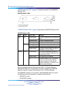
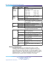
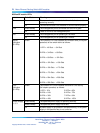
Label
Color/State
Meaning
The number of lit LEDs indicates the level of
CPU activity as follows:
1 LED = 12% 5 LEDs = 60%
2 LEDs = 24% 6 LEDs = 72%
3 LEDs = 36% 7 LEDs = 84%
CPU
Utilization
(8 LEDs)
Green
4 LEDs = 48% 8 LEDs = 100%
Green/Steady The specified power supply is operating
normally.
Amber/Steady The specified power supply has a fault.
Power
Supply
1, 2, 3
Off A power supply is not present in the specified
bay, or the power supply in the specified bay
is not turned on.
Green/Steady The specified fan is operating normally.
Fan 1, 2
Amber/Steady The specified fan has failed.
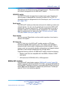
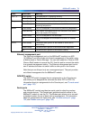
Green/Steady The temperature is normal for switch operation.Temp
Amber/Steady The temperature of the switch has exceeded
the maximum operating temperature.
Green/Steady The CPU subsystem on the module is
performing diagnostics.
Green/Blinking This module is providing active CPU functions
for the switch and is the master CPU module.
Amber/Steady The CPU subsystem is in a fault state.
Master
Off The CPU subsystem on the module is up and
is in standby mode.
Green/Steady The switch fabric portion of the module is online
and is load-sharing.
Amber/Steady The switch fabric portion of the module failed
diagnostics.
Online
Off The switch fabric portion of the module is
offline.
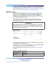
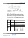
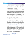
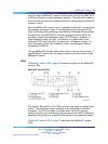
Ethernet management port
Ethernet management port on the 8691omSF module is an MDI
10/100BaseT port that allows out-of-band management of the switch
using a Web browser or Device Manager. You can also establish a Telnet
session to access the CLI. Use this port to connect the switch to a network
management station. The Ethernet management port has its own IP
address but does not switch traffic to other ports in the chassis.
Nortel Metro Ethernet Routing Switch 8600
Installation — Modules
NN46220-306 02.02 Standard
4.2 7 July 2008
Copyright © 2005-2007, Nortel Networks
.