


Page 208 of 906 NT5D11 and NT5D14 Lineside T1 Interface cards
553-3001-211 Standard 3.00 August 2005
cabled directly into the MMI terminal or modem; select the slave setting if
this card is cabled to another lineside T1 card in a daisy chain.
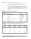
Tables 80 through 83 describes the proper dip switch settings for each type of
T1 link. After the card has been installed, the MMI displays the DIP switch
settings the command Display Configuration is used. See “Man-Machine T1
maintenance interface software” on page 225 for details on how to invoke this
command.
Table 80
Lineside T1 card—T1 Switch 1 (S1) dip switch settings
Dip Switch
Number
Characteristic Selection
1 MMI port speed selection On = 1200 baud
Off = 2400 baud
2 T1 signaling On = Ground start
Off = Loop start
3–6 XPEC Address for the lineside T1 card See Table 81
7 Not Used Leave Off
8 Reserved for SL-100 use Leave Off
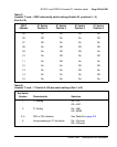
Table 81
Lineside T1 card – XPEC address dip switch settings (Switch S1, positions 3 – 6)
(Part 1 of 2)
XPEC
Address
S1 Switch
Position 3
S1 Switch
Position 4
S1 Switch
Position 5
S1 Switch
Position 6
00 Off Off Off Off
01 Off Off Off On
02 Off Off On Off
03 Off Off On On
04 Off On Off Off