


Page 862 of 906 QPC513 Enhanced Serial Data Interface card
553-3001-211 Standard 3.00 August 2005
Configuring the ESDI card
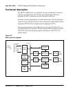
Configuring the ESDI card consists of setting the port addresses using the
address selection switch and setting the port interface options using the
jumper blocks. The system software must then be configured to recognize the
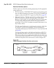
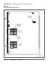
ESDI card. Figure 185 on page 864 shows the location of all option switches
and jumper sockets on the ESDI card.
Address switch settings
The two ESDI ports on the card are addressed in pairs such as 0 and 1, 2 and
3, and so on). The address is set using switch S2. The switch settings used to
select the address vary depending on whether the card is Style A or Style B.
The “Style” can be read on the printed circuit board silk screen. The address
of the card is set to match the device address defined in software.
Synchronous port address space is the same as asynchronous port address
space. When selecting an address for the ESDI card, make sure that it will not
conflict with an address currently being used by an asynchronous card.
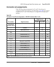
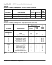
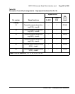
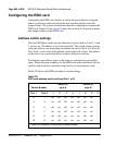
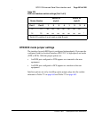
Table 270 shows the ESDI card address switch settings.
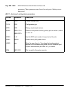
Table 270
ESDI card address switch settings (Part 1 of 2)
Device Number
Switch S2
style A
Switch S2
style B
Port 1Port 212341234
0 1 off off off on off off off *
2 3 on off off on off off on *
4 5 off on off on off on off *
6 7 on on off on off on on *
8 9 off off on on on off off *
10 11 on off on on on off on *
* Switch S2, position 4 is not used on style B cards.