


60 Index
server 11
features, front panel
diagram 12
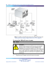
front bezel 27
G
grounding guidelines 36
I
illustration
modem 44
software feature key adapter 52
TLAN 19
inspecting
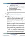
server inter ior 29
installation checklist 23
IRQ mapping table 18
K
keyboard
connecting to the server 47
description 22
keylock 52
M
M1 and CallPilot server network diagram 19
Metric wire conversion 37
modem
connecting to the server 48
description 21
DIP switches, setting 45
illustration 44
required equipment 44
monitor
connecting to the server 47
description 22
mouse
connecting to the server 47
description 22
N
network
protocols, supported 20
network interface cards 20
P
part number
Ethernet hub 22
keyboard 22
modem 21
monitor 22
mouse 22
PCI and ISA connectors
diagram 14
PDU 40
multiple PDUs 41
power and grounding 40
single PDU wiring diagram 41
peripheral devices
Ethernet hub 22
keyboard 22
modem 21
monitor 22
mouse 22
peripherals
connecting to the server 47
power connection
AC server 54
DC server 55
power distribution rationale 39, 40
power distribution unit
See PDU 40
power guidelines 36
power supply
bringing power and ground into the
PDU 42
DC wire gauge tables 36
grounding guidelines 36
Metric wire conversion 37
module installation 35
module location 34
overview 34
PDU 40
power distribution rationale 40
rack power and grounding 39
protocols, supported network 20
R
rack power and grounding 39
remote access
connectivity 21
Nortel CallPilot
1002rp Server Hardware Installation
NN44200-300 01.01 Standard
5.0 23 February 2007
Copyright © 2007, Nortel Networks Nortel Networks Confidential
.