


58 Appendix A Technical specifications
NN46110-313 02.01
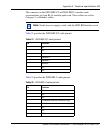
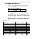
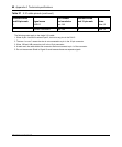
The following notes apply to the single V.35 DTE cable:
1. The term “no conn” means the wire is not connected to a pin in the 34-pin connector.
2. Wires 12B, 13A, and 14B connect to pin B in the 34-pin connector.
3. At each end, the cable shield and connector shell must connect respectively to pin A of the 34-pin connector and
pin 1 of the standard 28-pin connector.
4. Do not connect Shield to Signal Ground because these are separate signals.
5 CTSA pair 7A D
13 CTSB pair 7B no conn Note 1
6 DSRA pair 8A E
22 DSRB pair 8B J
20 DTRA pair 9A H
23 DTRB pair 9B no conn Note 1
8 DCDA pair 10A F
10 DCDB pair 10B no conn Note 1
18 LL pair 11A L
21 RL pair 11B N
25 TM pair 12A NN
26 M0<-SIGNAL GROUND pair 12B B Note 2
27 M1<-SIGNAL GROUND pair 13A B Note 2
28 M2 pair 13B no conn Note 1
1 SHIELD pair 14A A Notes 3,4
7 SIGNAL GROUND pair 14B B Notes 2,4
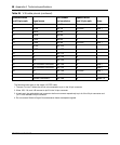
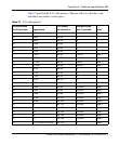
Table 26 V.35 cable pinouts (continued)
Standard-wired
end 28-pin male Signal name
Pair number
and conductor
Special-wired
end 34-pin male Notes