Data ModulesPassport 4400 Hardware Installation Manual
4-6
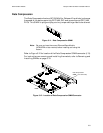
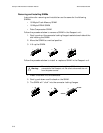
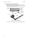
Attaching Cables to the High-Speed Data Module
Cable connections made in this procedure will depend on the specific site
requirements. If you are not sure of the connections required for the Passport
4400 unit, consult your system administrator.
For more information about cables, refer to Appendix A, Cable Diagrams.
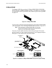
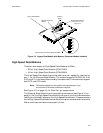
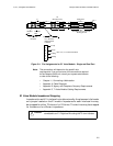
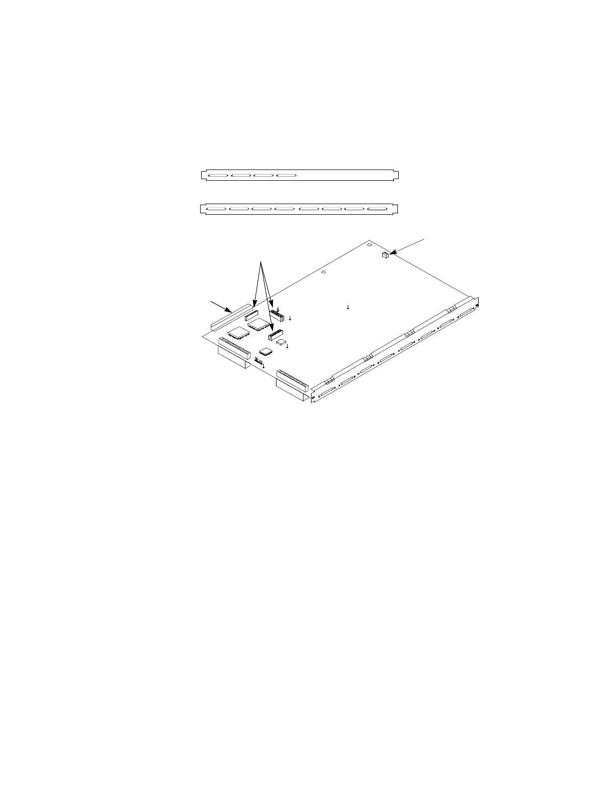
Figure 4-4. High-Speed Data Module
For further information about cables, refer to Appendix A, Cable Diagrams.
Back
4 Port
8 Port
Rear View
Stacking Connectors
for High-Speed Data
Module
Indicators
Module Switch Group
(see Figure 10-1 on
page 10-3)
Data Ports
50-pin Connectors
(see Figure 3-5 on
page 3-5 for pin
assignments)


