


Appendix A: Media Redirection Scenarios Page 247 of 258
Main Office Configuration for Survivable Remote Gateway 50 Configuration Guide
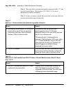
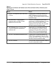
2 The SRG IP Phone registered to the main
office initiates a call transfer to a main
office IP Phone.
The SRG TDM telephone is put on hold. A
speech path is established between the SRG
IP Phone registered to the main office and the
main office IP Phone. The zone table
indicates interzone bandwidth usage.
3The Call Transfer key on the SRG
IP Phone registered to the main office is
pressed to complete the call transfer.
A speech path is established between the
SRG TDM telephone and the main office
IP Phone. The zone table indicates interzone
bandwidth usage.
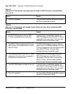
4 The call is released. The zone table indicates bandwidth usage for
the call is unreserved correctly.
Table 19
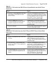
Scenario 2.2: Call transfer from main office IP Phone to SRG IP Phone in Normal Mode
(Part 1 of 2)
Event Result
1 An SRG TDM telephone calls a main office
IP Phone.
A speech path is established between the
SRG TDM telephone and the main office
IP Phone. The zone table indicates interzone
bandwidth usage.
2 The main office IP Phone initiates a call
transfer to an SRG IP Phone registered to
the main office.
The SRG TDM telephone is put on hold. A
speech path is established between the main
office IP Phone and the SRG IP Phone
registered to the main office. The zone table
indicates interzone bandwidth usage.
3The Call Transfer key on the main office
IP Phone is pressed to complete the call
transfer.
A speech path is established between the
IP Phone registered to the main office and the
SRG TDM telephone. The zone table
indicates intrazone bandwidth usage.
Table 18
Scenario 2.1: Call transfer from SRG IP Phone in Normal Mode to main office IP Phone
(Part 2 of 2)
Event Result