


12/29/2005
10
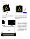
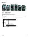
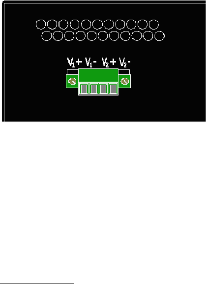
APPLYING POWER (Top View)
Unscrew & Remove the DC Voltage Input Plug from the top header.
Install the DC Power Cables into the Plug (observing polarity on unit).
Plug the Voltage Input Plug back into the top header.
All LED’s will flash ON Momentarily
Verify the Power LED stays ON (GREEN).
Note: Either V1 or V2 can be connected to power for minimal operation. For redundant power operation, V
1
and V
2
plugs
must be connected to separate DC Voltage sources. Use wire sizes of 16-28 gauge. The power cord should be limited to less
than 10 meters in order to ensure optimum performance.
Recommended 24V DC Power Supplies, similar to
100VAC/240VAC:
N-Tron’s NTPS-24-1.3, DC 24V/1.3A,
Operating temp range -10°C to +60°C
CONNECTING THE UNIT
For 300 Series fiber units, remove the dust cap from the fiber optic connectors and connect the fiber optic cables. For Fiber
Optic ports, the TX port on the near station should be connected to the RX port of the far end station, and the RX port should
be connected to the TX port of the far end station.
For 10Base-T ports, plug a Category 3 (or greater) twisted pair cable into the RJ45 connector. For 100Base-T ports, plug a
Category 5 (or greater) twisted pair cable into the RJ45 connector. Connect the other end to the far end station. Verify that
the LNK LED’s are ON once the connection has been completed. To connect any other port to another Switch or Repeater,
use a standard Cat5 straight through or crossover cable.