


(Revised 2010-11-15)
10
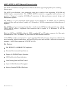
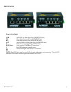
LED’s: The table below describes the operating modes:
LED
Color
Description
GREEN
Power is Applied
OFF
Power is OFF
!
RED
Controller HW Error
OFF
No Errors. Normal
Operation.
LNK
GREEN
Link between ports
established
OFF
No Link between ports
ACT
GREEN
Data is active between
ports
OFF
Data is inactive between
ports
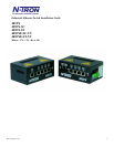
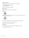
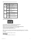
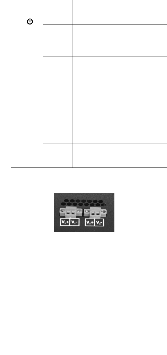
APPLYING POWER (Side View)
Unscrew & Remove the DC Voltage Input Plug(s) from the side header
Install the DC Power Cables into the Plug(s) (observing polarity).
Plug the Voltage Input Plug(s) back into the side header.
Tightening torque for the terminal block power plug is 0.22 Nm/0.162 Pound Foot.
All LED’s will flash ON Momentarily (including the Error LED)
Verify the Power LED stays ON (GREEN).
Verify the Error LED is OFF (after a few seconds).
Note: Only 1 plug is required to be connected to power input for minimal operation. For redundant
power operation, V
1
and V
2
plugs must be connected to separate DC Voltage sources. Use wire sizes
16-28 gauge.
Recommended 24V DC Power Supplies, similar to
100VAC/240VAC:
N-Tron’s NTPS-24-1.3, DC 24V/1.3A