


(Revised 2010-11-15)
13
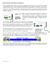
CONNECTING THE UNIT
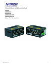
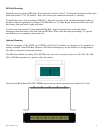
For 405FX & 405FXE units, remove the dust cap from the fiber optic connectors and connect the fiber
optic cables. The TX port on the 405FX should be connected to the RX port of the far end station. The
RX port on the 405FX should be connected to the TX port of the far end station.
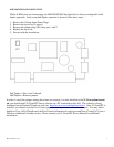
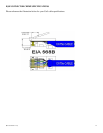
For 10/100 Base-TX ports, plug a Category 5 twisted pair cable into the RJ45 connector. Connect the
other end to the far end station. Verify that the LNK LED’s are ON once the connection has been
completed. For Switch to Switch or Switch to Repeater connections, use the X-port and a standard
Category 5 cable. To connect any other port (other than the X-Port) to another Switch or Repeater, use a
standard Category 5 crossover cable.
Warning: Creating a port to port connection on the same switch (i.e. loop) is an illegal operation and
will create a broadcast storm which will crash the network!
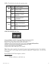
TROUBLESHOOTING
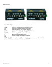
1. Make sure the (Power LED) is ON.
2. Make sure the ! (Error LED) remains OFF 3 seconds after initial power up.
3. Verify that Link LED’s are ON for connected ports.
4. Verify straight through cabling used between stations.
5. Verify crossover cabling used between switches or repeaters (non X-Port only).
6. Verify that cabling is Category 5 for 100Mbit Operation.
7. Verify TX is connected to far end RX and vise versa (405FX/FXE only).
SUPPORT
Contact N-TRON Corp. at:
TEL: 251-342-2164
FAX: 251-342-6353
www.n-tron.com
N-TRON_Support@n-tron.com
FCC STATEMENT
This product complies with Part 15 of the FCC-A Rules.
Operation is subject to the following conditions:
(1) This device may not cause harmful Interference
(2) This device must accept any interference received, including interference that may cause undesired
operation.