


4/26/2007
10
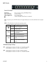
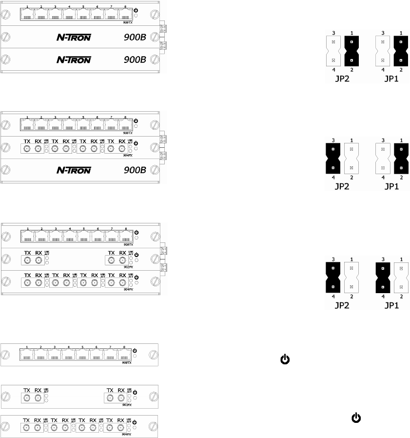
MODULE CONFIGURATION SETTINGS
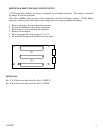
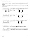
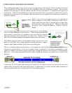
In order for the 900 Series modules to communicate properly the chassis must be populated with modules from the top
slot down as shown below. In addition, JP1 and JP2 jumpers (located on top side of all modules) must be configured as
indicated below.
Note: The power source must be disconnected from the 900B chassis prior to removing and inserting modules. This
unit is not hot swappable.
One Slot Configuration - When installing a single 902FX, 904FX, or 908TX module in
the top slot of the 900B chassis… Configure the module as follows:
JP1: pins 1 & 2 shorted
JP2: pins 1 & 2 shorted
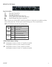
Two Slot Configuration - When installing two 902FX, 904FX, and/or 908TX modules
in the top two slots of the 900B chassis… Configure both modules as follows:
JP1: pins 1 & 2 shorted
JP2: pins 3 & 4 shorted
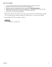
Three Slot Configuration - When installing three 902FX, 904FX, and/or 908TX
modules in all three slots of the 900B chassis… Configure all modules as follows:
JP1: pins 3 & 4 shorted
JP2: pins 3 & 4 shorted
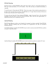
908TX Module - At power cycle, all LED’s flash on for approximately two seconds, and
then return to proper state. Green LED will light when Power is connected.
902FX & 904FX Modules - At power cycle, only the LED’s on the first port flash on to
indicate the reset condition, and then return to their proper state. All other reports remain
off during reset. This is normal behavior. Green LED will light when Power is
connected.