


4/26/2007
12
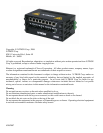
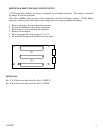
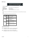
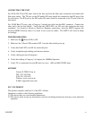
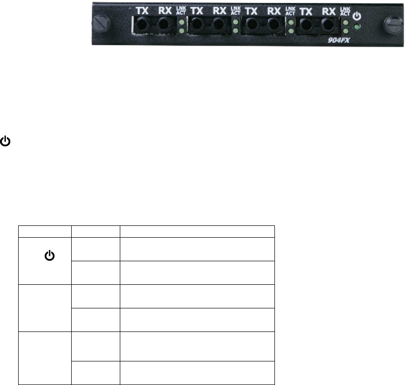
902/904 FX & FXE Module
From Left to Right:
TX Fiber Optic Transmit Port
RX Fiber Optic Receive Port
LNK Link LED (top LED) for Fiber Optic Port
ACT Activity LED (bottom LED) for Fiber Optic Port
Green LED lights when Power is connected
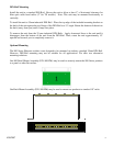
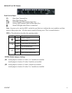
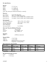
Note: At power cycle, only the LED’s on the first port flash on to indicate the reset condition, and then
return to their proper state. All other reports remain off during reset. This is normal behavior.
LED’s: The table below describes the operating modes:
LED Color Description
GREEN Power is Applied
OFF Power is OFF
LNK
GREEN Link between ports established
OFF No Link between ports
ACT
GREEN Data is active between ports
OFF Data is inactive between ports
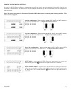
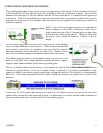
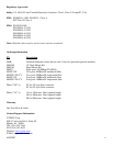
902/904 Module Jumpers Settings
JP1 install jumper in location 1-2 when 1 or 2 modules are installed
install jumper in location 3-4 when 3 modules are installed
JP2 install jumper in location 1-2 when 1 module are installed
install jumper in location 3-4 when 2 or 3 modules are installed