


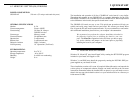
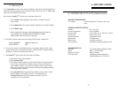
5 CONNECTING TO RELAYS
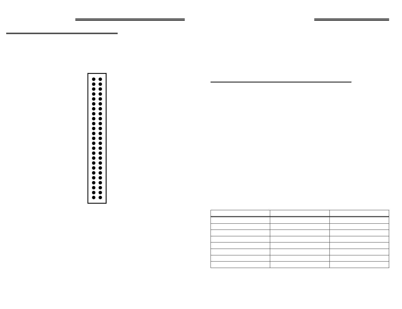
5.1 I/O CONNECTOR DIAGRAMS
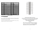
The CIO-RELAY08 and CIO-RELAY16 boards use a single 50 pin connector for sig-
nal interfacing. The CIO-RELAY24 and CIO-RELAY32 use two 50 pin connectors.
The pin-outs of the connector are shown here.
CIO-RELAY08 and CIO-RELAY16 Connector
PINS corresponding to relays 8 through 15 are not
connected on the RELAY08 version.
The form A relays used
on the /M versions have
NO
and
COM
connections only!
WARNING!
High voltages will be present on the CIO-RELAY boards when you
have connected high voltage inputs or outputs to the CIO-RELAY
connector. Use extreme caution! Never handle the CIO-RELAY
when signals are connected to the board.! DO NOT REMOVE
THE PROTECTIVE PLATES FROM THE CIO-RELAY
.
9
GND 50
15 NO 48
15 NC 46
14 COM 44
13 NO 42
13 NC 40
12 COM 38
11 NO 36
11 NC 34
10 COM 32
9 NO 30
9 NC 28
8 COM 26
7 NO 24
7 NC 22
6 COM 20
5 NO 18
5 NC 16
4 COM 14
3 NO 12
3 NC 10
2 COM 8
1 NO 6
1 NC 4
0 COM 2
49 +5V
47 15 COM
45 14 NO
43 14 NC
41 13 COM
39 12 NO
37 12 NC
35 11 COM
33 10 NO
31 10 NC
29 9 COM
27 8 NO
25 8 NC
23 7 COM
21 6 NO
19 6 NC
17 5 COM
15 4 NO
13 4 NC
11 3 COM
9 2 NO
7 2 NC
5 1 COM
3 0 NO
1 0 NC
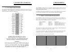
4 PROGRAMMING
The CIO-RELAY boards are easy to program. Eight bit registers located at the base
address and the base address plus an offset are written to control relays or can be read
to determine the state of relays.
In addition to direct I/O programming, the boards are fully supported by the powerful
Universal Library program as well as most third party application programs.
4.1 DIRECT I/O REGISTER PROGRAMMING
The CIO-RELAY family uses between one and four I/O addresses. Each address con-
trols 8 relays and the relays are controlled by writing to these registers. The base
address maps of the CIO-RELAY boards are shown below.
BASE ADDRESS Relay 0-7 Read/Write
BASE + 1 Relay 8-15 Read/Write (RELAY16, 24, 32)
BASE + 2 Relay 16-23 Read/Write (RELAY24, 32)
BASE + 3 Relay 24-31 Read/Write (RELAY32 only)
The registers are written to and read from as a single 8 bit byte. Each bit controls an
output (write) or represents the state of a relay (read).
All registers are read left to right. The leftmost bit being the most significant bit. Fol-
lowing this format bit 7 of BASE+0 corresponds to relay 7 and bit 0 to relay 0.
To construct a control word, use the following table:
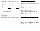
801287
40646
20325
10164
883
442
221
110
HEX VALUEDECIMAL VALUEBIT POSITION
6