


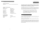
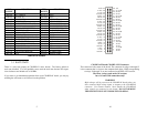
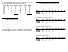

For example, to assemble the control byte that will turn on relays 0. 1. 3. 5 and 7 we
can see from the chart below we need to write decimal 171 (hex AB):
171AB
111111OP0
212212OP1
004004OP2
818818OP3
00160010OP4
3213220120OP5
00640040OP6
128112880180OP7
WEIGHTON=1DECIMALWEIGHTON = 1HEXRELAY
4.2 PROGRAMMING NOTES
WRITE = CONTROL: Write a byte to the register to control the relays. A one in the
relay bit position turns the relay on.
READ = STATUS: Read the status of the relay control register. A one in the relay
bit position indicates the relay is on.
ON & OFF for FORM C RELAYS:
On means that FORM C relay common is in contact with the Normally Open contact.
Off means that FORM C relay common is in contact with the normally closed contact.
7
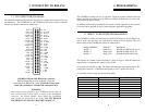
4.3 DETAILED RELAY CONTROL I/O MAP
The following section provides a detailed description of the register map and relay
control registers.
Base Address +0 (applicable to all CIO-RELAY series boards).
RELAY
OP7 OP6 OP5 OP4 OP3 OP2 OP1 OP0
BIT No. 76543210
HEX Value 804020108421
DECIMAL 1286432168421
Base Address +1 (RELAY16, 24 and 32 only)
RELAY
OP15 OP14 OP13 OP12 OP11 OP10 OP9 OP8
BIT No. 76543210
HEX Value 804020108421
DECIMAL 1286432168421
Base Address +2 (RELAY24 and 32 only)
RELAY
OP23 OP22 OP21 OP20 OP19 OP18 OP17 OP16
BIT No. 76543210
HEX Value 804020108421
DECIMAL 1286432168421
Base Address +1 (RELAY32 only)
RELAY
OP31 OP30 OP29 OP28 OP27 OP26 OP25 OP24
BIT No. 76543210
HEX Value 804020108421
DECIMAL 1286432168421
8