


5
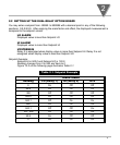
2.3 ELECTRICAL CONNECTION AND SPECIFICATION
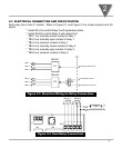
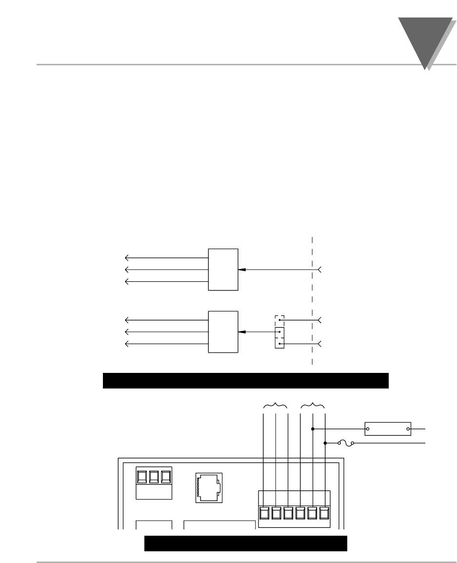
Each relay has a form C contact. Refer to Figure 2-1 and Figure 2-3 to locate contacts and S5
switch.
* Install S5-A to control Relay 2 with hysteresis action.
* Install S5-B to control Relay 2 with setpoint HI.
* TB3-1 is a normally closed contact of relay 1.
* TB3-2 is a normally open contact of relay 1.
* TB3-3 is a common contact of relay 1.
* TB3-4 is a normally closed contact of relay 2.
* TB3-5 is a normally open contact of relay 2.
* TB3-6 is a common contact of relay 2.
Figure 2-3. Electrical Wiring for Relay Connections
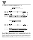
Figure 2-4. Dual-Relay Connections
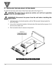
10-1. Dual-Relay Option Board
2
J1
J2
TB1
123
123456
1
6
TB2
TB3
EXTERNAL
LOAD
N
L
FUSE
RELAY 1 RELAY 2
NC1
NO1
CM1
NC2
NO2
CM2
TB3—1
TB3—2
TB3—3
NC1
NO1
CM1
TB3—4
TB3—5
TB3—6
NC2
NO2
CM2
RELAY1
RELAY2
K1
K2
A
B
S5
P5
SETPOINT LOW OUTPUT
HYSTERESIS OUTPUT
SETPOINT HIGH OUTPUT