


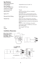

Installation
The LV-1101 Series Level Switches are supplied with a 2" x 1" TT bushing
threaded in place with 2 to 3 wraps of Teflon tape, which must be intact or
renewed if bushing and switch are separated before assembly in tank. Apply
a minimum of 2 to a maximum of 3 wraps of Teflon tape to the male threads
of the bushing. This is especially important if the unit is to be used in metal
fittings where coarse threads could bind if not lubricated.
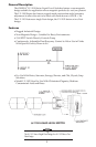
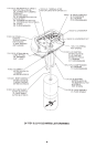
Thread the unit into the tank and tighten until a good, no leak seal is obtained.
Make sure that the arrows molded on the body casting and printed on the
label are pointed vertically downward.
Remove the cover and test for proper switch action by applying multimeter
probes to the COM, NO and NC terminals of the microswitch while
actuating the switch lever arm.
The unit is supplied with the adjusting spring in the relaxed condition.
Leave the spring in the relaxed condition and fill the vessel until the float is
submerged. If the switch is actuated, proceed with the electrical wiring.
If the specific gravity of the working fluid is too low to lift the float and
actuate the switch, then the buoyancy adjustment feature must be used. To
adjust the buoyancy, turn the leadscrew CLOCKWISE until the switch is
actuated. Lower the liquid level until the float is clear of the liquid and the
switch is de-actuated. Raise the liquid level again until the float is submerged
and the switch actuates. If no further spring bias adjustment is required,
proceed with wiring.
Electrical Wiring
1. WIRING THE LV-1101/1102 WITH THE STRAIN RELIEF CABLE FITTING:
a. Remove the gland nut and tapered rubber grommet from the strain
relief cable fitting and slide them over the cable with the gland nut
going on first.
b. Strip the outer jacket of the cable back 5
1
/
2
inches. Strip the insulation
from the individual conductors approximately
1
/
4
".
c. Spade Lugs supplied with each switch. Remove them from the terminal
strip and crimp or solder to appropriate leads.
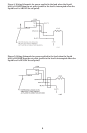
d. Feed cable up through cable fitting and attach leads to terminal strip per
Figure 1 or Figure 2 Wiring Schematics, below.
e. Push the rubber grommet into the conical hole in the cable fitting,
allowing enough cable to protrude from the opposite side to allow some
slack in the leads attached to the terminal strip. Grip the cable to
prevent rotation and thread the gland nut onto the cable fitting to seal
the grommet tightly to the cable.
Check the match of the outside diameter of the cable with the inside
diameter of the grommet. No more than .020" of play should be
evident.
NOTE
3