


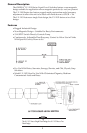

Check the match of the outside diameter of the cable with the
inside diameter of the grommet. No more than .020" of play
should be evident.
NOTE
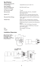
2. WIRING THE LV-1101/1102 W/OPTION ‘D’ WITH STRAIN RELIEF
CABLE FITTING.
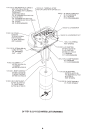
a. Remove the gland nut and tapered rubber grommet from the strain
relief cable fitting and slide them over the cable with the gland nut
going on first.
b. Strip the outer jacket of the cable back 2 inches. Strip the insulation from
the individual conductors approximately
1
/
4
".
c. Each microswitch is supplied with 3 flag slip-on terminals. Remove
from the microswitch and crimp or solder to the appropriate leads.
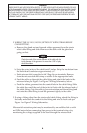
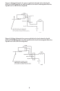
d. Feed the cable up through the cable fitting and attach the leads to the
microswitches per Figure 1 or Figure 2 Wiring Schematics, below.
e. Push the rubber grommet into the conical hole in the cable fitting. Slide
the cable thru until the end of the jacket is flush with the inboard end of
the cable fitting. Grip the cable to prevent rotation and thread the gland
nut onto the cable fitting to seal the grommet tightly to the cable.
3. If using a fitting other than the strain relief cable fitting, attach the fitting to
the body and attach the conduit to the fitting and wire to local code per
Figure 1 or Figure 2 Wiring Schematics.
Microswitch actuation point may be monitored by an audible click or with
an OHM meter before connecting line power to the terminal strip or by
monitoring the voltage supplied to the load through the microswitch.
4
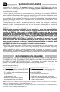
WARNING
THESE DEVICES ARE NOT EXPLOSION-PROOF. IF THESE LEVEL SWITCHES ARE INTENDED FOR USE
WITH FLAMMABLE LIQUIDS, OR IN HAZARDOUS AREAS, THE MECHANICAL RELAY INSIDE CAN BE
MADE INTRINSICALLY SAFE WHEN PROPERLY WIRED TO AN INTRINSICALLY SAFE RELAY SWITCH,
SUCH AS OMEGA’S LVC 550 SERIES INTRINSICALLY SAFE RELAYS. THEY MUST BE INSTALLED IN
ACCORDANCE WITH THE NATIONAL ELECTRIC CODE (NEC) BY PERSONNEL EXPERIENCED WITH
INTRINSIC SAFETY WIRING.