


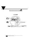
FINAL INSTALLATION
6
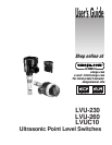
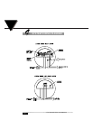
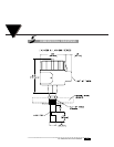
For Ultrasonic Point Level Switches
3
CONTACT MODELS
Follow the instructions below:
1. Drill a suitable hole in the vessel or pipe wall and tap for 3/4” NPT. If this
walled vessel or material is not suitable for threading, weld or braze a bush-
ing to accept the sensor.
2. Screw the sensor in the threaded section and make sure that there is a good
seal. Use a pipe compound or sealing tape compatible with the materials and
avoid excessive tightening.
3. Run the power and control wiring cable to the electronic control unit.
Observing all applicable electrical codes and proper wiring procedures.
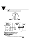
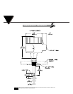
CONTROL UNIT
Refer to the typical installation diagram and control unit dimensions when
installing the control unit. Follow steps 1 and 2 below for remote mounted elec-
tronic units. Steps 3 through 7 are common for both the integral electronic units
and remote electronic units.
1. Mount the remote control unit on any suitable wall, panel, etc. making sure
there is adequate clearance for wiring.
2. Remove the PC board by removing the screws. Drill a suitable size hole in the
control unit housing for a conduit fitting (if so required).
3. Remove the cover from housing. To complete wiring, either leave or remove
the electronics printed circuit board in the housing on remote units and
remove the encapsulate electronics in integral units.
CAUTION: Never remove unit from a vessel with power and/or output
control cables connected to the electronic control unit inside the housing
to avoid cable damage.
4. Wire the unit as desired. Refer to the wiring diagram inside the cover.
Note: All wiring, conduit and fittings should conform to local electrical
codes. In a hazardous location, a conduit seal should be installed within
18 inches of the control unit housing. Use a drain seal in vertical conduit
run to prevent condensation from entering the control unit. OMEGA
assumes no responsibility for improperly wired units.
5. Replace the printed circuit board, if removed, or the encapsulated electronics.
Make certain that the wires are dressed carefully to prevent pinching between
the cover and the housing.
6. Replace the housing cover.