


3
MATERIALS OF CONSTRUCTION
BODY / COVER: Aluminium with Teflon Imprenated Hard Anodized (PolyLube) Surfaces
PROBES: 316 Stainless Steel
SEALS - COVER, PROBES: Buna N
RATINGS / SPECIFICATIONS
TEMPERATURE: 10 F to 180 F
CONDUIT CONNECTION: 1/2” NPT
ELECTRICAL RATING: 10 amp. 250VAC maximum; 1/2 amp. 125VDC; 1/4 amp. 250VDC; 5 amp.
125VAC lamp load. Note: each pole must be the same polarity to utilize these ratings.
MICROSWITCHES: Mechanical S.P.D.T. (Single Pole Double Throw)
INTERNAL WIRING CONNECTIONS: Screw Clamp
NEMA STANDARDS: NEMA 1 (General Purpose); NEMA 4 (Watertight & Dusttight); NEMA 7 (Haz-
ardous Locations, Class I Groups B, C, & D); NEMA 9 (Hazardous Locations, Class II, Groups E, F, &
G); NEMA 12 (Oiltight and Driptight); and NEMA 13 (Oiltight and Dusttight).
UL LISTINGS: Industrial Control Equipment for use in Hazardous Locations, Class I, Groups B,C, & D
and Class II, Groups E, F, & G
MAINTENANCE
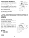
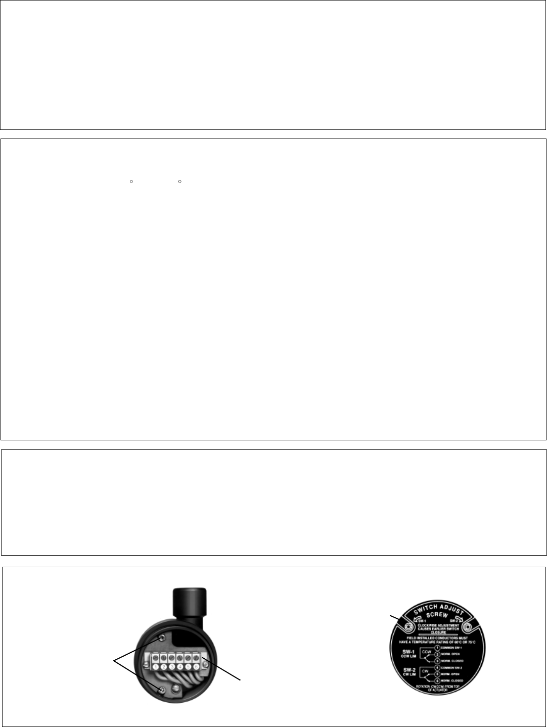
The BVLS normally requires no maintenance. However, in certain situations the switch adjustment
screws may require some attention to either advance or retard the cam actuated switch point. This
enables precise adjustment of the switch timing throughout the life of the unit.
Switch Adjustment
Screws
Terminal Strip
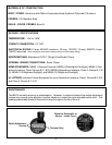
Electrical Schematic as
Shown - Inside Cover