


DP3300 Series User’s Manual
Page14
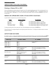
Display Options
On pushing SETUP key while the display is flashing SYS , the display briefly shows 'dSP OPt' (for display option) and then
the current Display Option setting. Following display options are selectable. Use ^v key to step thru these options. Once the
desired Display Option is shown, push SETUP key to enter the setting and go to set Display Time.
Option
Display Description
SCAN SCAN Scan all channels that are turned on.
HIGH POINT HIGH Pt Display peak value of all channels that are turned on.
LOW POINT LO Pt Display low reading of all channels that are turned on.
CH1 – CH2 CH1 – CH2 Channel 1 differentialwith respect to channel 2
CH2 – CH1 CH1 – CH2 Channel 2 differentialwith respect to channel 1
ELAPSED TIME ELPSEd t Elapsed time
‘Display Time’ Setup
The first parameter in system setup mode is the DISPLAY TIME. This determines how many seconds a channel's reading is
displayed before scanning to the next channel. The display will first show 'dSPLy t' (for Display Time), and then the present
setting in seconds. Use ^v key (ref. Setup For High Scale) to set the desired DISPLAY TIME value. Once the desired DISPLAY
TIME value is displayed, push SETUP key to enter that value and go to Setup For Relay Latch/Non-Latch
Audio Alarm ON/OFF
The next step lets you program the buzzer ON or OFF. The display will either read 'ALR ON' or 'ALR OFF'. To make an
alternate selection, push ^v key. After making any change or to retain current setting, push SETUP key. This will take you to the
very beginning of setup mode.
Cold Junction Setting
The next parameter is the cold junction reference temperature. The display will first show 'COLd JN', and then the cold
junction temperature will be indicated. IF NECESSARY
, use the ^v key to adjust until the display reads proper temperature.
Once the correct temperature is displayed, push PROG key to enter that setting and go to Controller Calibration.
NOTE 1:
The unit should be powered up for at least fifteen to twenty minutes before any adjustments are made to the cold
junction reading.
NOTE2: Cold Junction temperature is the temperature at the connector where thermocouple connects (and forms the juntion) into
the unit. IT IS NOT THE AMBIENT TEMPERATURE.
Calibration Mode
After setting the Cold Junction Reference temperature, the next step is calibration of channels. This allows easy calibration of
each channel without the instrument scanning from channel to channel. The display will show channel input reading in the form
'x-nnnnn' (where x=channel number and nnnnn is the process reading).
NOTE 1
: ONLY channels that are turned ON will be displayed at this time!
NOTE 2: Only analog channels can be calibrated.
Thermocouple Calibration Procedure
Note
: Make sure the unit is reading correct cold junction temperature before calibration.
If incorrect, adjust as described in the "Program For Cold Junction" section.
For calibrating a thermocouple Channel, the following steps should be performed. Note that calibrating one channel will
automatically calibrate the other channel. Also, only one type of thermocouple input needs to be calibrated i.e. J,K,T or E. For
example, if the calibration is done for a type K thermocouple, types J, T, and E are automatically calibrated.