


DP3300 Series User’s Manual
Page22
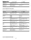
NOTE: Process value for respective relay must be below limit value for it to reset. Other wise the key sequence will be ignored.
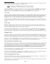
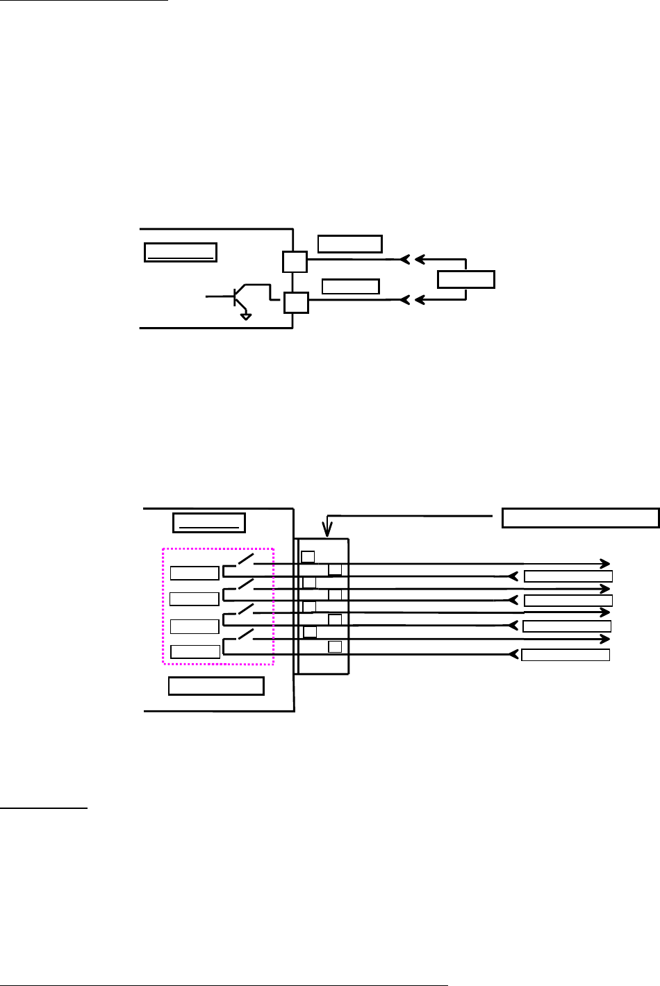
Open Collector (solid state) output Option:
DP3300 units can be ordered with either open collector outputs or electro-mechanical relays. (Check model number printed on
the unit for option). If ordered with open collector outputs, then these outputs are programmed during Setup to operate as either
Normally Open (NO) or Normally Closed (NC). The default setting is Normally Open.
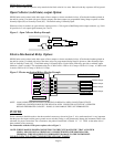
Whenever a limit is reached, an open collector output provides a 5 Vdc signal at 50milliamp on the output connector, eg.. Limit
#1 provides its 5 volt output signal between pins 1 and 2.
Figure 1. Open Collector Hookup Example
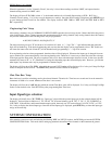
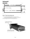
Electro-Mechanical Relay Option:
DP3300 units can be ordered with either open collector outputs or electro-mechanical relays. (Check model number printed on
the unit for option). If ordered with relays, then these relays are programmed during Setup to operate as either Normally Open
(NO) or Normally Closed (NC). The default setting is Normally Open. Each of these limit relays provides a switched output
whenever a limit is reached. The maximum rating for a 120Vac unit is 120Vac @ 0.5 amp or 28 Vdc @ 1.0 amp. A 240Vac unit
is rated at 240Vac @ 0.25 amp. or 28Vdc @ 1.0 amp.
Figure 2. Electro-mechanical Relays Hookup Example
NOTE: LOOK UNDER SPECIFICATIONS FOR RATING ON RELAYS & OPEN COLLECTOR OUTPUTS.
UNDER NO CONDITION SHOULD THE RELAYS & OPEN COLLECTOR OUTPUTS BE OPERATED
BEYOND THEIR RATED CAPACITY. DOING SO CAN DAMAGE THE UNIT PERMANENTLY.
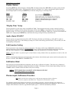
POWER
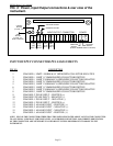
Power connection should be made to the three terminal connector as shown in figure 3. Also, make note that it is very important
that the power line inputs and the power ground are not switched. Doing so will permanently damage the instrument. Refer to the
schematic for proper connections. For convenience, the printed circuit board is labeled L1 L2 GND on the under side of
three terminal power connector.
For instruments with the 12Vdc power option, refer to Figure 3.
NOTE: WHILE MAKING POWER CONNECTION TO THE UNIT, MAKE SURE THAT AC POWER
LINE L1 OR L2 IS NOT ACCIDENTALLY CONNECTED INTO THE GROUND (GND)
TERMINAL. THIS WILL RESULT IN PERMANENT DAMAGE TO THE INSTRUMENT.
DOUBLE CHECK THE CONNECTIONS BEFORE APPLYING POWER!!
1
2
Instrument
-OUTPUT
+OUTPUT
LOAD
LIMIT RELAYS
OUTPUT CONNECTOR
LIMIT # 1
LIMIT # 2
LIMIT # 3
LIMIT # 4
1
2
3
4
5
6
7
8
120 VAC @ 0.5 AMPS
120 VAC @ 0.5 AMPS
120 VAC @ 0.5 AMPS
120 VAC @ 0.5 AMPS
Switched Output
Switched Output
Switched Output
Switched Output
Instrument