


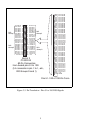

5 REGISTER MAPS
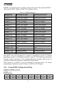
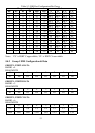
The PCI Controller, a PLX-9052, has four configuration, control, and status registers
(Table 5-1). They are described in the following section.
Table 5-1. I/O Region Register Operations
8-bit byteDigital I/O registersBADR3
N/AN/ABADR2
32-bit double wordPCI I/O-mapped config. registersBADR1
32-bit double wordPCI memory-mapped configuration
registers
BADR0
OperationsFunctionI/O Region
5.1 BADR0
BADR0 is reserved for the PLX-9052 configuration registers. There is no reason to
access this region of I/O space.
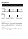
5.2 BADR1
BADR1 is a 32 bit register for control and configuration of interrupts.
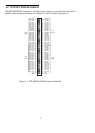
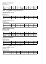
5.2.1 INTCSR Configure
BADR1 +4C hex
LEVEL/EDGEXINTCLRXISAMDXXX
89101112131432:15
READ/WRITE
INTEINTPOLINTXXXPCINTX
01234567
Note: For applications requiring edge triggered interrupts (LEVEL/EDGE bit 8 = 1),
the user must configure the INTPOL bit for active high polarity (bit 1=1).
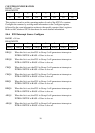
The INTCSR (Interrupt Control/Status Register) controls the interrupt features of the
PLX-9052 controller. As with all of the PLX-9052 registers, it is 32-bits in length.
Since the rest of the register have specific control functions, those bits must be
masked off in order to access the specific interrupt control functions listed below.
9