


M-4271/0707, pg. 15 of 26
Q
1
/ Q
2
= K
1
/ K
2
Q
1
is the flow rate of the new gas
Q
2
is the flow rate of the original calibration gas
K
1
is the K factor of the new gas
K
2
is the K factor of the original calibration gas
Q
1
= (K
1
/ K
2
) Q
2
If K
2
is larger than K
1
then linear results will only be achieved if the unit
does not exceed 5(K
1
/ K
2
)VDC for the full scale output.
Example 1
For a 0-200sccm unit calibrated for air the flow at 5.0VDC would be
200sccm. The K factor for air is 1. If the unit is used with Helium (K factor
1.454 relative to air) then the flow at 5VDC (i.e. the maximum flow) would
be (1.454/1)200 = 290.8 sccm
Example 2
For a 0-10.0 l/min unit calibrated for Argon the flow at 5.0VDC would be
10.0l/min. The K factor for Argon is 1.45. If the unit is used with Carbon
Dioxide (K factor 0.74) then the flow rate 5.0VDC would be
(0.74/1.45)10.0 = 5.10l/min
The accuracy of readings using K factors is not as good as that achieved
for the calibration gas. The accuracy obtained (typically ±3% for K factors
similar to the calibration gas) depends on the gas being used and the flow
rate.
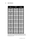
For a list of common K Factors see Section J.
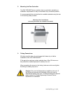
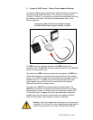
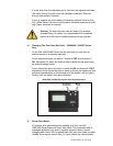
4. Changing The Flow Rate Set-Point (Using An External Voltage
Source)
The required flow rate is selected by adjusting the set-point voltage. The
normal control signal voltage is 0-5VDC with 0VDC corresponding to zero
flow and 5VDC being equivalent to the maximum rated flow of the unit.
This input is linear and scaleable allowing different flow rates within the
range of the unit to be selected. For example:
For a flow range of 0-500sccm:
A 5 VDC Input Signal would correspond to a flow rate of 500sccm
If a flow rate of 300sccm were required then the set-point would
be:
(300 ÷ 500) × 5 = 3.0VDC