


M-4271/0707, pg. 8 of 26
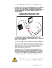
4. Electrical Connections
Caution: Incorrect wiring may cause severe damage to the unit.
Applying an AC voltage (115VAC or 230VAC) directly to the unit
will cause damage. Read the following instructions carefully
before making any connections.
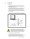
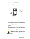
a) Overview
The FMA 3200/3400 Series provides a 0-5VDC analog output proportional
to the flow rate. This output may be connected to a display, data
acquisition system or voltmeter with an impedance of greater than 2.5 kΩ
(kilo ohms).
The flow controller needs to be supplied with a 0-5 VDC set point signal to
enable control. On the FMA 3400/3400ST Series this may be generated
internally by altering the set-point potentiometer on the front panel of the
unit.
A stable D.C. power supply is required to operate the unit. The voltage
and current requirements depend on the configuration of the unit. Full
details may be found in the Specification section of this manual.
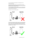
Connecting wires should be as short as possible to avoid voltage drops.
Twisted conductor cable should be used if the length of the wiring is to be
longer than 2 meters.
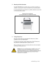
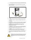
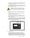
Units are supplied with either a 6 pin mini DIN type connector (requires
mating cable assembly), a 9 Pin D Sub connector or 15 Pin D Sub
connector.
Caution: Cutting off the integrated connectors on the unit IS
NOT RECOMMENDED and will void the product warranty. Mating
cables should be ordered along with each unit.
Electrical connections to the units are made as detailed in the following
sections.