


Page 17
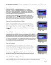
Setup For Channel Calibration
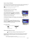
After setting the Cold Junction Reference temperature, the next step is a display of channels for calibration purposes. This
allows easy calibration of each channel without the instrument scanning to the next channel. The display will show the
channel input reading in the form 'x-nnnnn' where x=channel # and nnnnn is the channel reading.
NOTE
: ONLY channels that are turned ON will be displayed at this time!
Press SETUP key to step the display to the next channel.
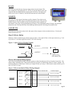
Input Range Setup (for current and voltage):
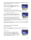
Voltage Range Setup (0-10vdc, 0-5vdc)
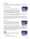
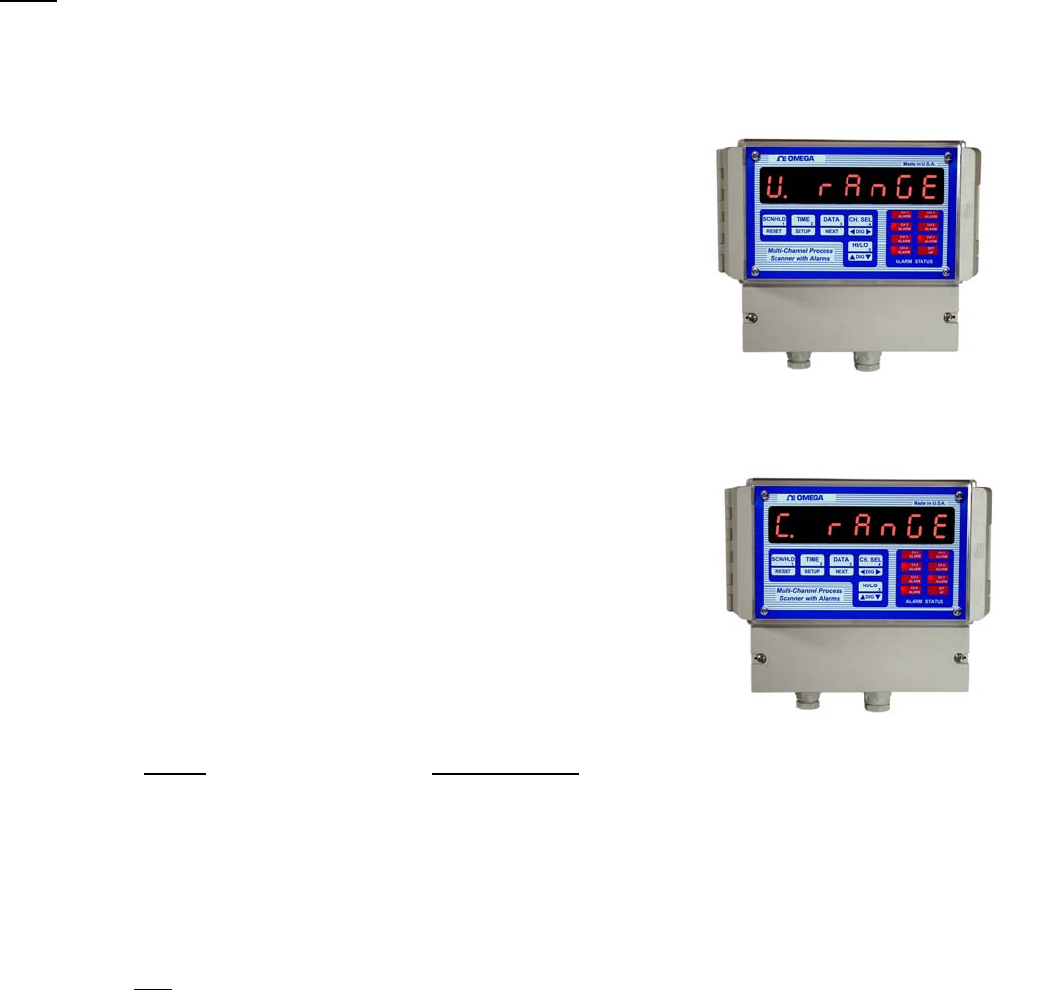
After all the enabled channels have been displayed, the VOLTAGE range may
be setup. The display will briefly show 'U rAnGE' (for "Voltage Range")
followed by the current setting. Use SDIGT key (ref. Setup For High Scale)
to set the desired VOLTAGE value. Once the desired value is displayed, push
SETUP key to enter that value and go to the next step.
Voltage Range Setup (for millivolt inputs)
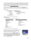
For Millivolt input units, the display first shows 'HV rnGE' (for "High Voltage Range"). After the High Voltage range
is set, the display shows 'LV rnGE' (for "Low Voltage Range"). Enter values for respective inputs.
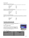
Current Range Setup
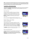
After VOLTAGE range has been set, the CURRENT range may be set. The
display will briefly show 'C RANGE' (for "Current Range") followed by the
current setting. Use SDIGT key (ref. Setup For High Scale) to set the desired
CURRENT value. Once the correct CURRENT range is displayed, push SETUP
key to enter that value and return to 'SYS CH' display.
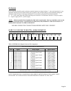
Correct Range Settings
The following RANGE values should be entered for various inputs:
INPUT
RANGE VALUE
0-5 Vdc 5.000
0-10 Vdc 10.000
0-100 Mv 100.0
4-20 Ma. (loop current) 20.00
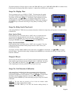
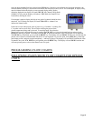
Thermocouple Calibration Procedure
Note
: Make sure the unit is reading correct cold-junction temperature before calibrating.
If incorrect, adjust as described in the "Setup For Cold Junction" section.
For a thermocouple channel calibration (type J T.C), following steps should be performed. Note that calibrating any
channel automatically sets the calibration for all channels. Also, only one type of thermocouple input needs to be
calibrated i.e. J,K,T or E. For example, if the calibration is done for a type K thermocouple, types J, T, and E are
automatically calibrated.
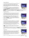
1. Connect a thermocouple calibration source to channel 1.
2. Dial in 1100 degrees centigrade (Note: unit must be programmed for displaying in centigrade).