


Card Setup
OMG-COMM2-EX Page 2
Card Setup
The OMG-COMM2-EX contains several jumper straps which must be set for
proper operation.
Address Selection
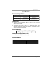
Each port on the OMG-COMM2-EX occupies eight consecutive I/O locations. A
DIP-switch is used to set the base address for these locations. Be careful when
selecting the base address as some selections conflict with existing ports. The
following table shows several examples that typically do not cause a conflict.
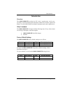
SW1 sets the I/O address for port 1 of the OMG-COMM2-EX and SW2 sets the
address for port 2.
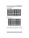
Address Binary Switch Position Setting
Hex A9 A0 1 2 3 4 5 6 7
280-287 1010000XXX Off On Off On On On On
2A0-2A7 1010100XXX Off On Off On Off On On
2E8-2EF 1011101XXX Off On Off Off Off On Off
2F8-2FF 1011111XXX Off On Off Off Off Off Off
3E8-3EF 1111101XXX Off Off Off Off Off On Off
300-307 1100000XXX Off Off On On On On On
328-32F 1100101XXX Off Off On On Off On Off
3F8-3FF 1111111XXX Off Off Off Off Off Off Off
Figure 1 - Address Selection Table
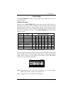
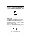
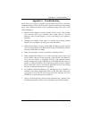
The following illustration shows the correlation between the DIP-switch setting
and the address bits used to determine the base address. In the example below,
address 300 is selected as a base. Address 300 in binary is XX11 0000 0XXX
where X = a non-selectable address bit.
ON
1 2 3 4 5 6 7 8
ENA3A9
Figure 2 - DIP-Switch Illustration
Note: Setting the switch ‘On’ or ‘Closed’ corresponds to a ‘0’ in the address,
while leaving it ‘Off’ or ‘Open’ corresponds to a ‘1’.
Refer to Appendix A for common address contentions.