


2
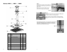
Models: PMD.5 — PMD1 — PMD2
Part Description Qty.
Mount Assembly Hard-
ware
A Top Projector Plate 1
B Bottom Projector Plate 1
C Pipe Drop Assembly 1
D Plastic Cover 1
E Ceiling Plate 1 Bag
F Hex Screw: ¼”-20 X ¼” 1 (d)
G Screw: ¼”-20 X 3/8” 2 (c)
H Hex Screw: ¼”-X 5/8” 4 (d)
I Hex Screw: ¼”-X ½” 6 (d)
J Lag Bolt: 5/16” X 3” 4 (e)
K Plastic Plugs 14 (b)
Hex Wrench 1 (d)
7
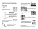
Step 5
Slide the bottom projector mounting plate onto
the previously installed top projector mounting
plate. (Fig. 11)
Note: Make sure that the cables don’t get
pinched while sliding the plates together.
Important: Always secure projector plates by installing 3/8”
screws (G) into holes on front edge of plates.
Additional security can be provided by installing small pad-
locks through security slots at the rear of the projector plates.
(Fig. 12)
Fig. 11
Fig. 12
Attach cables to the projector. Turn projector ON, and make pitch
and keystone adjustments as per the projector manufacturers
instructions. For additional pitch/tilt, use the three adjustment
knobs on top of the PMD mount (Fig. 13).
Fig. 13