


6
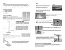
Repeat this procedure for the remaining threaded inserts.
(Fig. 10)
Note: A 1” plastic spacer (3) is included for projectors
with uneven mounting surfaces. Trim the plastic spacer to
the required length, and install on appropriate mounting
screw.
Fig. 8
Fig. 9
Fig. 10
Once all mounting screws have been installed, square up the projector mounting plate,
and then tighten the mounting screws securely.
Caution: Do not force or over tighten the mounting screws, or damage to the projector
may occur.
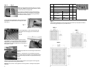
Step 5
Determine required mounting screw size (4, 5 or 6 mm)
for projector. Note: Consult projectors owners’ manual
for screw sizes and mounting holes.
Lay projector on table with mounting surface face up.
Place grid section of bottom projector mounting plate
onto top of projector in desired mounting orientation
(horizontal or vertical). (Fig. 6)
Fig. 6
Using a pencil or felt tipped pen, mark the locations of
the projectors threaded inserts onto the grid for refer-
ence. (Fig. 7)
Fig. 7
Place a large washer (1) over mounting screw, and
then insert screw through grid at marked location.
(Fig. 8)
Lift the projector mounting plate and place a second
large washer (1) onto the end of the screw, followed by a
metal spacer (2). Loosely thread (2-3 turns) screw as-
sembly into the chosen threaded insert on the bottom of
the projector. (Fig. 9)
3
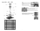
Part Projector Mounting Hardware Qty. Bag
1 Large Washer 8 (a)
2 Metal Spacer: 3/8” 4 (a)
3 Plastic Spacer: 1” 1 (b)
PMD–.5 /PMD–1
PMD-2
4 Screw:
5mm x 25mm
Screw:
6mm x 25mm
4 (c)
5 Screw:
4mm x 25mm
Screw:
5mm x 25mm
4 (c)
6 Screw:
3mm x 25mm
Screw:
4mm x 25mm
4 (c)
Hardware Bags
Step 1
Verify that the dimensions (H x W) of the mounting lands on y0ur projector fall within
the mounting grid footprint for your PMD mount.
PMD .5
PMD 1
PMD 2