E5ZN-DRT
Features
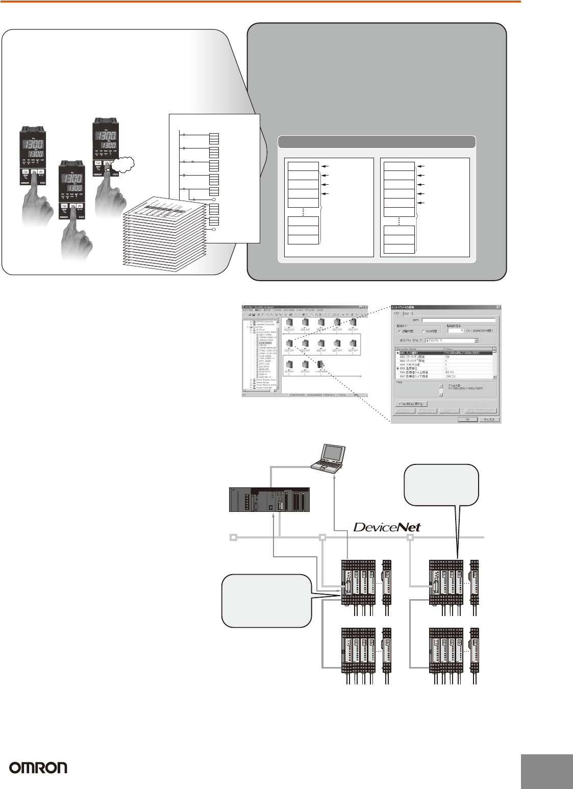
Startup Time Is Six Times Faster and No Communications Programs Are Needed
Manage All E5ZN Together from the DeviceNet Configurator
Improved Maintenance with Monitoring, Comment, and Copying Functions
Previously, a time-consuming process of creating
communications programs, debugging, and checking
operations was required for the Temperature Controller to
communicate with the PLC.
● For example, setting 10 Units required 60 minutes.
● Incorrect inputs were a concern.
● Separate debugging for each Unit was needed.
DeviceNet Communications Units enable high-speed data
communications by allocating settings and monitoring
parameters in the PLCs I/O Memory Area, contributing to greater
reductions in the time required for communications program
development.
● For example, set 10 Units in 10 minutes.
● Batch download using the personal computer.
● Debugging is easy using the personal computer.
Wd 0 and 1
Wd 2 and 3
Wd 4 and 5
Wd 6 to 37
OUT enabled
Control ON/OFF
AT executing
Set value (SV)
User-specified
allocations
are possible.
Wd 38
Wd 98
Wd 99
Wd 100
Wd 0 and 1
Wd 2 and 3
Wd 4 and 5
Wd 6 and 7
Comm status
Control ON/OFF
AT executing
Alarm output
User-specified
allocations
are possible.
Wd 38
Wd 8 to 37
Wd 98
Wd 99
Wd 100
Process value (PV)
OUT Area IN Area
PLC Memory
NG
Beep
Beep
Beep
ASC ← Converts SP data into ASCII.
← Calculates FSC.
Trigger
DM000
K
Sd
FSC
Trigger
C
S
Sf
← Sends command.TDX
Trigger
S
C
N
Send Ready Flag
← Receives response.RXD
Receive Completion Flag
D
C
N
← Checks end code.
Normal completion
CMP
Receive Completion Flag
De
#3030
← Checks FCS.
FCS check OK
FCS
Receive Completion Flag
C
D
D'f
CMP
Df
D'f
No-protocol Example
D'f
Use the DeviceNet Configurator for E5ZN
initial settings and temperature control wiring
to enable immediate execution.
DeviceNet
Master
POWER
BPS
UNIT
ERROR
SD/RD
OUT1
OUT2
SUB1
SUB2
E5ZN
POWER
BPS
UNIT
ERROR
SD/RD
OUT1
OUT2
SUB1
SUB2
E5ZN
POWER
BPS
UNIT
ERROR
SD/RD
OUT1
OUT2
SUB1
SUB2
E5ZN
POWER
BPS
UNIT
ERROR
SD/RD
OUT1
OUT2
SUB1
SUB2
E5ZN
E5ZN
● Measure the heater control time (RUN
time monitor) to manage heater life
expectancy.
● Monitor supply voltages, such as those
for Temperature Controller and
Communications Unit power supplies,
and network power supplies.
● User-specified names can be set for
each heater and Communications Unit,
enabling the location of errors to be
checked quickly.
● Upload/download Temperature Controller
parameters to the Communications Unit.
This shortens the time required to
replace Temperature Controllers.
POWER
BPS
UNIT
ERROR
SD/RD
OUT1
OUT2
SUB1
SUB2
E5ZN
POWER
BPS
UNIT
ERROR
SD/RD
OUT1
OUT2
SUB1
SUB2
E5ZN
POWER
BPS
UNIT
ERROR
SD/RD
OUT1
OUT2
SUB1
SUB2
E5ZN
POWER
BPS
UNIT
ERROR
SD/RD
OUT1
OUT2
SUB1
SUB2
E5ZN
POWER
BPS
UNIT
E5ZN
ERROR
E5ZN-SCT24S
SD/RD
OUT1
OUT2
SUB1
SUB2
Maintenance data
Control data
POWER
BPS
UNIT
ERROR
SD/RD
OUT1
OUT2
SUB1
SUB2
E5ZN
POWER
BPS
UNIT
ERROR
SD/RD
OUT1
OUT2
SUB1
SUB2
E5ZN
POWER
BPS
UNIT
ERROR
SD/RD
OUT1
OUT2
SUB1
SUB2
E5ZN
POWER
BPS
UNIT
ERROR
SD/RD
OUT1
OUT2
SUB1
SUB2
E5ZN
E5ZN
POWER
BPS
UNIT
ERROR
SD/RD
OUT1
OUT2
SUB1
SUB2
E5ZN
POWER
BPS
UNIT
ERROR
SD/RD
OUT1
OUT2
SUB1
SUB2
E5ZN
POWER
BPS
UNIT
ERROR
SD/RD
OUT1
OUT2
SUB1
SUB2
E5ZN
POWER
BPS
UNIT
ERROR
SD/RD
OUT1
OUT2
SUB1
SUB2
E5ZN
POWER
BPS
UNIT
E5ZN
ERROR
E5ZN-SCT24S
SD/RD
OUT1
OUT2
SUB1
SUB2
DeviceNet
Configurator
Check the actual
operating time
of the heater.
Check the settings
for the heater of
oven No. 3.
http://www.ia.omron.com/
2
(c)Copyright OMRON Corporation 2007 All Rights Reserved.


