E5ZN-DRT
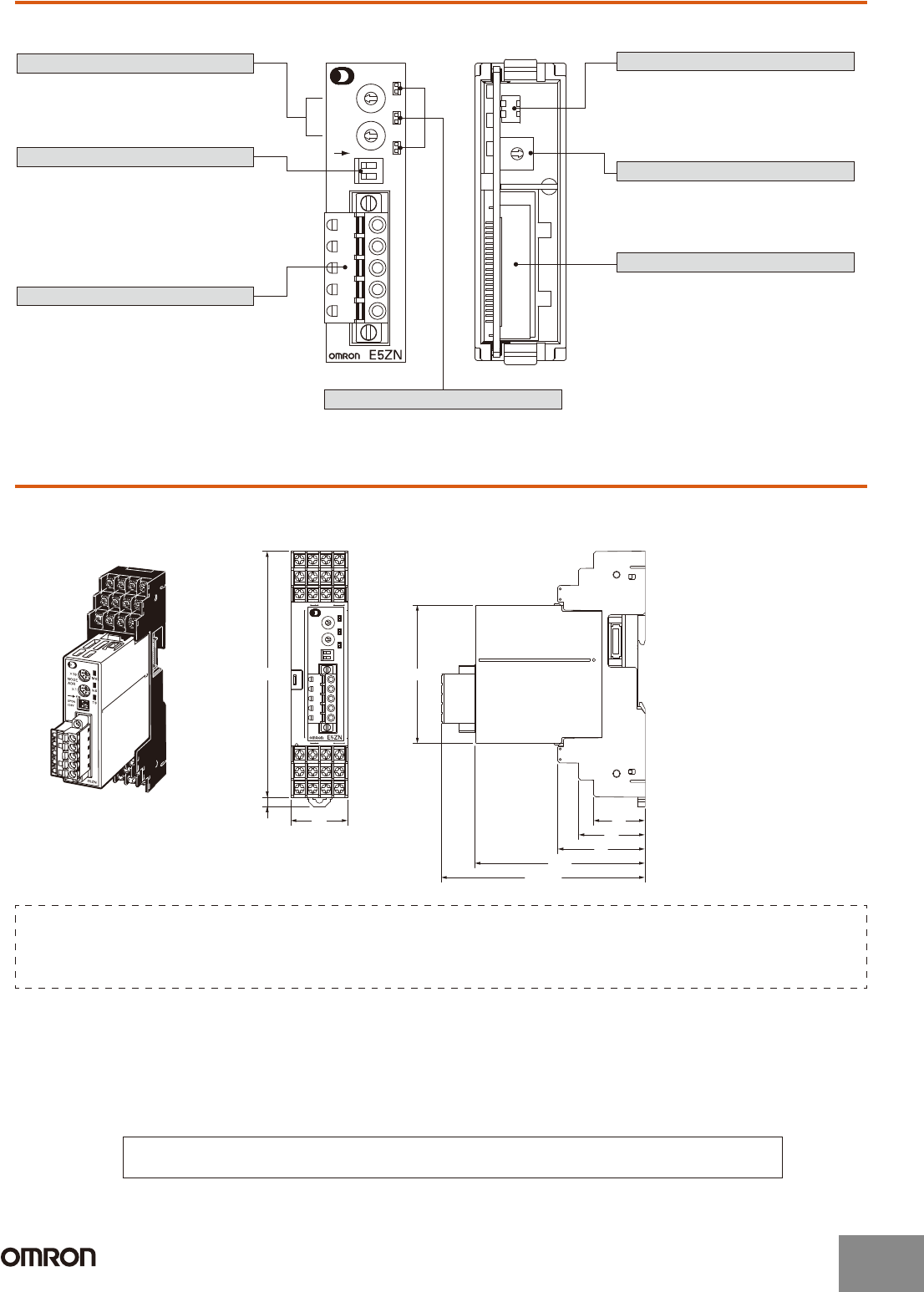
Nomenclature
Dimensions
Note: All units are in millimeters unless otherwise indicated.
0
7
8
9
A
B
C
D
E
F
1
2
3
4
5
6
×10
NODE
ADR
×1
ON
UP/DN
COPY
MS
NS
TS
E5ZN-DRT
Front Panel Rotary Switches
Front Panel DIP Switch
DeviceNet Connector
Back Panel DIP Switch
Pin 1: I/O allocation setting switch
Pin 2: Not used (Set to OFF.)
Back Panel Rotary Switch
Terminal Unit Connector
Connects to DeviceNet communications
cables. Power for DeviceNet communica-
tions is also supplied though this
connector. An FCK2.5/5-STF-5.08AU
connector (Phoenix Contact) is
provided.
Used to set the node address when
functioning as a DeviceNet slave.
Connects to the E5ZN-SCT24S
Terminal Unit.
Used to set the maximum unit number
when simple I/O allocation is used.
Used to specify whether the connection
configuration and I/O allocation is set
using simple I/O allocation or Configurator
I/O allocation.
Used to copy (backup) parameters between
the Temperature Controllers and DeviceNet.
UP/DN (Pin 2): Sets the copy operationmode
(i.e., upload or download).
COPY (Pin 1): Starts the copying.
Indicators
E5ZN-DRT
30
72.8
27
35
46
89.6
(107.5)
4.7
130
Dimensions when Mounted to the
E5ZN-SCT24S Terminal Unit
Note: Be sure to read the precautions for correct use and other precautions in the following user’s manuals before using the
Communications Unit.
E5ZN-DRT DeviceNet Communications Unit Operation Manual (Cat. No. H119)
DeviceNet Operation Manual (Cat. No. W267)
In the interest of product improvement, specifications are subject to change without notice.
ALL DIMENSIONS SHOWN ARE IN MILLIMETERS.
To convert millimeters into inches, multiply by 0.03937. To convert grams into ounces, multiply by 0.03527.
http://www.ia.omron.com/
5
(c)Copyright OMRON Corporation 2007 All Rights Reserved.


