


Time Delay
The time delay can be selected by the user during set up. It can be adjusted
from 15 seconds up to 30 minutes. For additional information on how to adjust
it, please read the SENSOR ADJUSTMENT & PROGRAMMING section of this
installation manual.
Light Level
When the sensor is set for occupancy sensor Mode
2 (Auto-ON/OFF) the light level feature prevents
the sensor from automatically turning the lights
ON if there is already enough light in the area. To
adjust the light level, please read the SENSOR
ADJUSTMENT & PROGRAMMING section of this
installation manual.
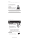
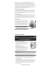
Coverage Area
The RS-250 has a maximum range of 180 degrees
and a coverage area of 600 sq. feet (56 sq. meters).
The sensor must have a clear and unobstructed
view of the coverage area. Objects blocking the
sensor’s lens may prevent detection thereby
causing the light to turn OFF even though
someone is in the area.
Windows, glass doors, and other transparent barriers will obstruct
the sensor’s view and prevent detection.
INSTALLATION & WIRING
WARNING
Disconnect power to the wall switch box by turning OFF
the circuit breaker or removing the fuse for the circuit before
installing the RS-250, replacing lamps, or doing any electrical work.
1. Prepare the switch box.
After the power is turned OFF at the circuit
breaker box, remove the existing wall plate and
mounting screws. Pull the old switch out from the
wall box.
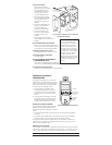
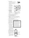
2. Identify the type of circuit.
In a Single Pole Circuit (see Fig. 2), two single
wires connect to two screws on the existing
switch. A ground wire may also be present and
connected to a ground terminal on the old switch.
A neutral wire should also be present in the wall
box.
CAUTION - FOR YOUR SAFETY: Connecting a proper ground to the
sensor provides protection against electrical shock in the event of
certain fault conditions. If a proper ground is not available, consult
with a qualifi ed electrician before continuing installation.
Only connect the RS-250 to a Single Pole Circuit. The RS-250 is not suitable
for 3-way switching. If the existing wiring does not match the description for a
Single Pole Circuit, you should consult with a qualifi ed electrician.
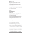
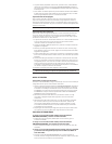
3. Prepare the Wires.
Tag the wires connected to the existing switch, so
that they can be identifi ed later. Disconnect the
wires. Make sure the insulation is stripped off the
wires to expose their copper cores to the length
indicated by the “Strip Gage,” (in Fig. 3) (approx.
1/2 inch).
25'
(7.6m)
12'
(3.7m)
Fig. 1: Sensor Coverage Area
www.wattstopper.com/athome
Ground
HOT (power from
circuit box)
LOAD
(power
to lamp)
NEUTRAL
Fig. 2: Typical Single
Pole Switch
Wiring
Strip Gage
1/2"
12.7 mm
Fig. 3: Wire
Stripping