


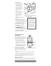

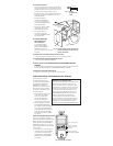

4. Wire the sensor.
Twist the existing wires
together with the wire leads
on the RS-250 sensor as
indicated below. Cap them
securely using the wire
nuts provided (See Fig 4).
• Connect the green or non-
insulated (copper) GROUND
wire from the circuit to
the green terminal on the
RS-250.
• Connect the NEUTRAL wire
from the circuit and from
the lamp (LOAD) to the
white wire on the RS-250.
• Connect the power wire
from the circuit box (HOT)
to the black wire on the
RS-250.
• Connect the power wire to the
lamp (LOAD) to the red wire on the
RS-250.
5. Put the RS-250 in the wall box.
Position the lens above the ON/OFF button
(lens at top, button at bottom) and secure it
to the wall box with the screws provided.
6. Restore power to the circuit.
Turn ON the breaker or replace the fuse.
7. Test the sensor’s operation.
See TEST MODE.
8. Review SENSOR ADJUSTMENT &
PROGRAMMING below.
If you want to make adjustments, follow the
instructions in SENSOR ADJUSTMENT & PROGRAMMING, below.
9. Attach the new cover plate.
Secure it to the wall box with the screws provided.
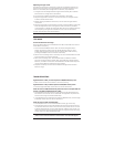
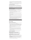
SENSOR ADJUSTMENT &
PROGRAMMING
To program the RS-250, you use controls
located under the ON/OFF button. The wall
switch cover plate must be removed to gain
access to the mode button and adjustment
trimpots under the ON/OFF button.
1. Firmly grasp the side edges of the
Lock Bar and gently pull it away from
the switch face until it clicks. Do NOT
attempt to pull the Lock Bar off of the
switch!
2. Firmly grasp the side edges of the ON/
OFF button. Slide the button downward
approximately 1/2 inch to expose the
mode button and adjustment trimpots.
Setting up the Operating Mode
Select the operating mode by pressing the
Mode button. The amber LED behind the
switch button blinks to indicate the selected
mode:
• One blink indicates Mode 1 (Vacancy Sensor Operation), Manual-ON/OFF,
Auto-OFF
• Two blinks indicate Mode 2 (Occupancy Sensor Operation), Auto-ON/OFF
w/manual control and reset to auto (after 5 minutes of vacancy)
To change the mode, press the Mode button. The LED blinks to indicate the
selected mode. It repeats the selected mode three times. After that, the unit
operates in the indicated mode.
Adjusting the Time Delay
Turn the right trimpot counter-clockwise to reduce the amount of time the load
will remain on after the last motion detection (minimum = 15 seconds). Turn the
same trimpot clockwise to increase this time delay (maximum = 30 minutes).
Warning: Do not overturn the time delay adjustment trimpot!
TOP
Green
–
>
GROUND
Terminal
Black
–
>
HOT (power
from circuit box)
L
L
White
–
>
NEUTRAL
Red
–
>
LOAD (power
to lamp or fan)
Fig. 4: Sensor orientation, wire connections
and wall box assembly
TOP
INDOOR USE ONLY
Lock Bar
Mode Button
& Adjustment
Trimpots
Slide down
ON/OFF
Button
Time Delay
15
minutes
Mode
Level
06006r1
1–Manual
2–Auto-ON
Fig. 5: Sensor Adjustment Controls
Initial Power-up Delay
There is an initial warm-up
period the fi rst time power is
applied to the unit and after
a power failure lasting more
than 5 minutes. If the sensor
is in Mode 2, (automatic-ON) it
may take up to 1 minute before
the lights turn ON. However,
the lights can be turned
ON/OFF manually by pressing
the ON/OFF button at any time
when power is supplied to
the unit.