


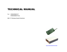
WiSER 2400 Technical Manual Version 2.16 Copyright 2001-2005, OTC Wireless, Inc. All Rights Reserved Page 7 of 32
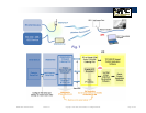
1.1.4 Selecting the Serial Mode for WiSER2400.Plus
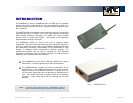
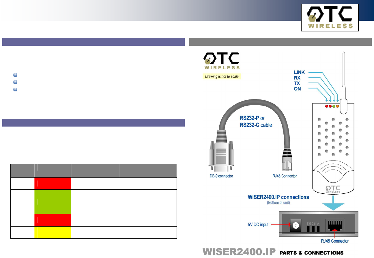
WiSER2400.IP
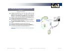
The WiSER2400.Plus has a 4-position dipswitch next to the mini Phoenix
connector for selecting the serial operating mode:
RS-232
RS-485
(select RS-485 and half-duplex)
RS-422
(select RS-485 and full-duplex)
The factory default has the dipswitch set in the RS-232 mode. Please refer to
Fig. 4 for details in setting the dipswitch for different operating modes.
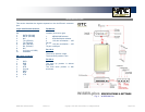
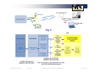
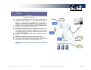
1.1.5 Status LEDs
Power on the WiSER2400, the LEDs on the front panel should exhibit the
following patterns:
(Refer to Fig. 3 and Fig. 4)
LED Color Light Blinking
Pattern
Indication
ON RED
Steady on
Proper power is
supplied
Steady on
Unit is linked to a
wireless system
RX GREEN
Steady blink
Unit is not linked to
any wireless system
TX RED
On when
transmitting
Unit is transmitting
RF signal
LINK
YELLOW
Blinking
Serial Mode
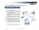
Secure the WiSER2400 at the desired location with the provided Velcro (for
WiSER2400.IP) or DIN Rail mounting kit (for WiSER2400.Plus) once the
hardware is setup and works properly with the intended host device or
equipment.
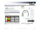
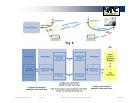
Fig. 3 WiSER2400.IP