


TM
TM
11
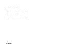
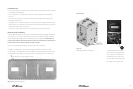
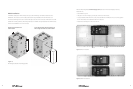
Plastic bushing,
DC side
Figure 11: DCA bushing
Note: The DCA will be held rmly in place when the DCC (FX cover) is secured at the end of the
installation.
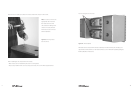
To install an ACA:
• Follow the separate ACA instructions for mounting to the FX.
• Line each ACA up with its conduit hole in the AC chassis.
• When aligned, move the AC chassis snug against the ACAs after the ACA installations.
• Press a 1” plastic bushing from inside the AC chassis out to the ACA through each previously
removed knockout, sliding the AC chassis against the ACAs until snug.
• Install two M5 X 25mm screws (provided in ACA hardware kit) in each ACA and tighten securely.
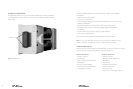
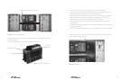
Installation of the AC Chassis and DC Chassis
To install the chassis:
• Hold each chassis up to its respective mounting holes on the FW-MP.
• Place one M6 X 10mm machine screw (provided with the FW-MP) in each corner, tightening
only enough to keep the chassis in place.
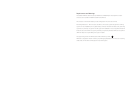
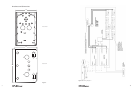
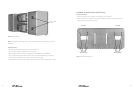
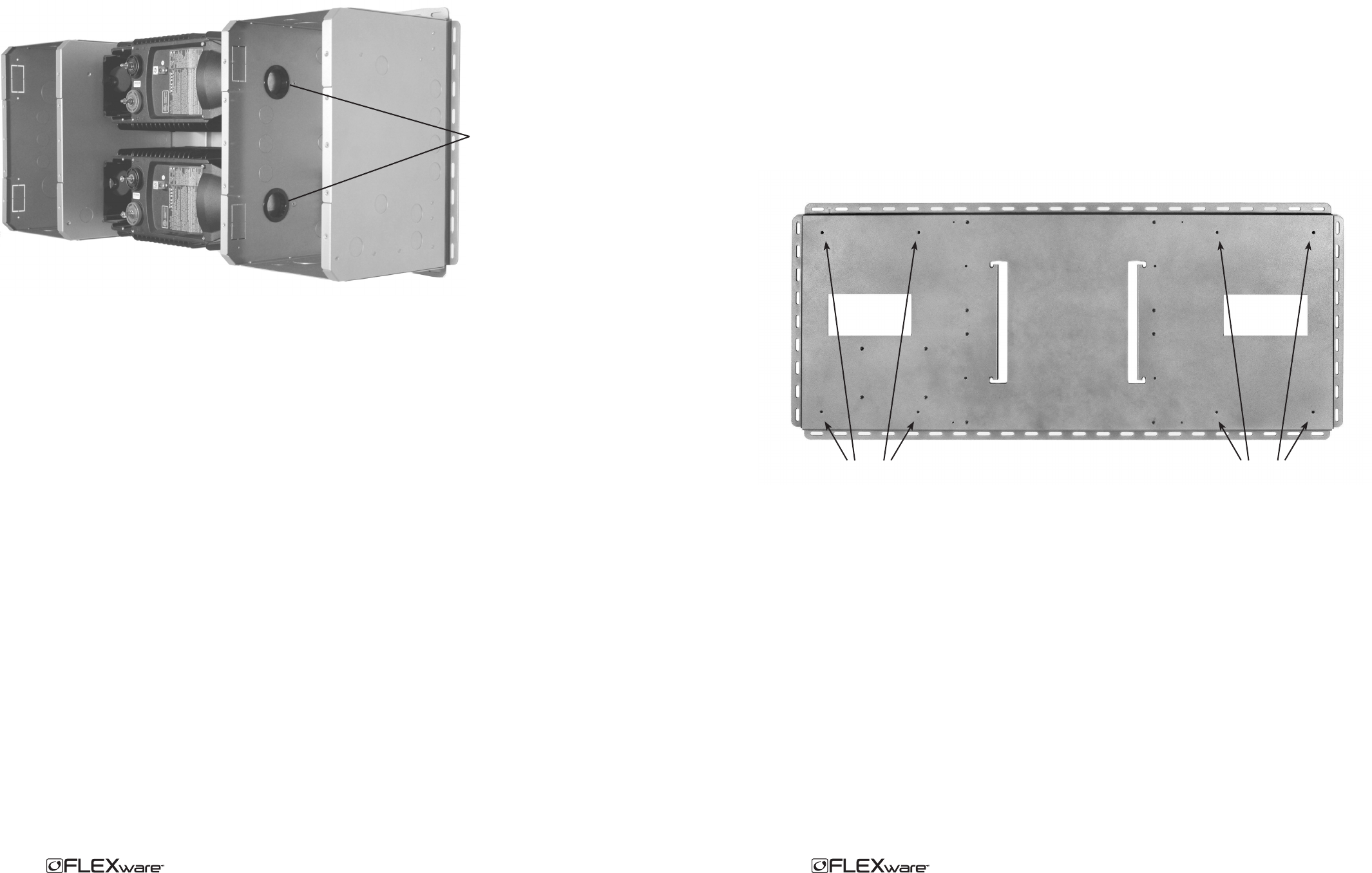
AC side DC side
Figure 7: Chassis Mounting Holes
AC Chassis
Mounting Holes
DC Chassis
Mounting Holes
8