


TM
TM
9
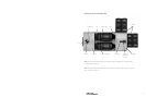
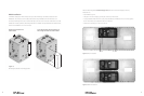
Clear plastic AC cover
AC Conduit Plate
Figure 9: FX Series Inverter/Charger
DC Wiring
Cover (DCC)
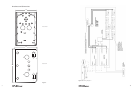
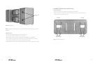
Figure 8: AC and DC chassis mounted
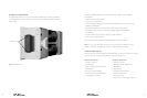
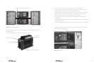
With each chassis loosely mounted, the AC Conduit Adapter (ACA) and DC Conduit Adapter (DCA)
are installed on each FX.
• Remove the clear plastic AC cover and AC Conduit Plate from each FX.
Corrugated Conduit installs between the chassis
• Line up either the ACA or DCA on its respective side of the FX, starting at the top.
• To attach a DCA, line up its two screw holes with the upper and lower right DCC screw holes.
• When lined up, loosely install the upper screw to hold the DCA in place.
• Slide the DC chassis over snug against the DCA (the screw slots in each chassis are oval-shaped
to allow for movement) so the DCA lines up with the conduit adapter hole on the chassis.
• Install the plastic bushing from inside the chassis into the DCA (see Figure 11).
• After inserting the bushing into the top DCA, the remaining DCA will line up and the other
bushing installed.
• With all the DCA’s aligned with the DC chassis and the bushings installed, tighten the DC Chassis
screws against the FW-MP.
• The single screws holding each DCA in place can be removed later when the DCC’s are installed.
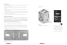
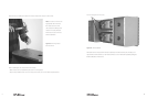
A single screw holds each DCA conduit adapter in place. Slide the DC chassis against each DCA
and line it up with the plastic bushing.
Figure 10: DCA in place
10