


48 Packard Bell oneTwo M3600 AIO Computer Service Guide
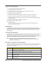
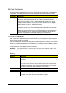
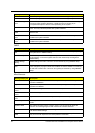
DIM Code Checkpoints
The Device Initialization Manager (DIM) gets control at various times during BIOS POST to initialize different
system busses. The following table describes the main
checkpoints where the DIM module is accessed.
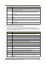
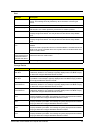
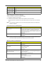
POST Error Indicators
When a system error is detected during POST (Power On Self Text), the Setup utility will switch to diagnostic
mode and display a POST error message.
POST error messages tell users what failure the system has detected. Some error messages could be related
to a hardware device. Others may indicate a problem with a device configuration. In some cases an error
message may include recommendations for troubleshooting or require that you press the Enter key to display
recommendations. Follow the instructions on the screen. It is recommended that you correct the error before
proceeding, even if the computer appears to boot successfully.
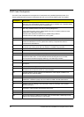
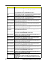
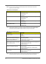
Memory
Checkpoint Description
2A Initialize different buses and perform the following functions: Reset, Detect, and Disable
(function 0); Static Device Initialization (function 1); Boot Output Device Initialization
(function 2). Function 0 disables all device nodes, PCI devices, and PnP ISA cards. It also
assigns PCI bus numbers. Function 1 initializes all static devices that include manual
configured onboard peripherals, memory and I/O decode windows in PCI-PCI bridges,
and noncompliant PCI devices. Static resources are also reserved. Function 2 searches
for and initializes any PnP, PCI, or AGP video devices.
38 Initialize different buses and perform the following functions: Boot Input Device
Initialization (function 3); IPL Device Initialization (function 4); General Device Initialization
(function 5). Function 3 searches for and configures PCI input devices and detects if
system has standard keyboard controller. Function 4 searches for and configures all PnP
and PCI boot devices. Function 5 configures all onboard peripherals that are set to an
automatic configuration and configures all remaining PnP and PCI devices.
IMPORTANT If your system fails after you make changes in the Setup menus, reboot the computer, enter
Setup again and load Setup defaults to correct the error.
Message Description
Gate20 Error The BIOS is unable to properly control the mainboard’s Gate A20 function, which
controls access of memory over 1 MB. This may indicate a problem with the
mainboard.
Multi-Bit ECC Error This message will only occur on systems using ECC enabled memory modules.
ECC memory has the ability to correct single-bit errors that may occur from faulty
memory modules.
A multiple bit corruption of memory has occurred, and the ECC memory algorithm
cannot correct it. This may indicate a defective memory module.
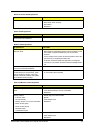
Parity Error Fatal Memory Parity Error. System halts after displaying this message.
RAM R/W test failed This message is displayed by the AMIBIOS8 when the RAM read/write test fails.
CMOS Memory Size
Wrong
The base memory (memory below 1MB) size that is reported in the CMOS (offset
15h) mismatches with the actual size detected. This condition may occur when the
hole is set at 512K base memory or when CMOS is corrupted.