


AV3,AVM3/AVT3,AVL3
NOTES
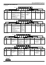
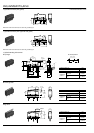
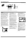
2-(3) .110 Quick-connect terminal
5.5
7.1
11.0
16.1
8.8
NO
NC
C
±0.1
±0.15
0.6 max.
2.4
9.5
7.6
6.4
2.8
0.5
4.0
8.4
(
P.T.
)
6.7
7.7
3.3
-0.05
+0.1
2.4
2.5
±0.3
±0.1
±0.1
(
O.P.
)
±0.3
±0.2
±0.1
2.4 dia.
+0.1
-0.05
1.2 dia.
±0.05
19.8
±0.3
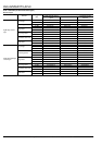
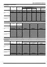
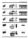
As for the dimensions of lever types, dimensions other than terminals are same as self-standing solder terminal.
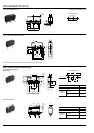
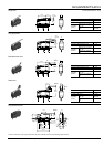
mm General tolerance: ±0.25
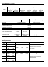
1.Regarding fastening of switch body
In fastening the switch body, use flat
filister head M2.3 screws, with tightening
torque of not more than 0.29N·m.To
prevent loosening of the screws, it is
recommended that spring washers be
used with the screws and adhesive be
applied to lock the screws.
After mounting the switch and making
wiring connections, the insulation
distance between ground and each
terminal should be confirmed as
sufficient.
The positioning of the switch should be
such that the pushbutton or actuator for
the switch should not directly apply force
to the operating section in the free
condition.For a pushbutton, the force
from the pushbutton should be applied in
a perpendicular direction.
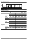
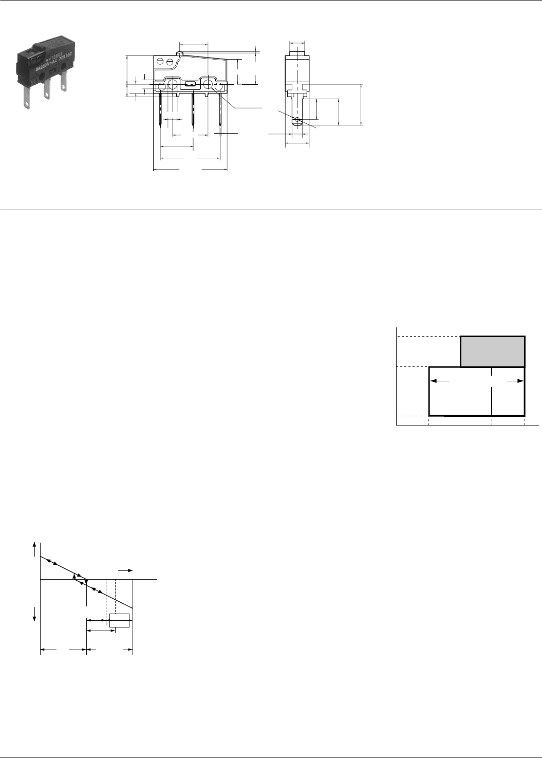
In setting the movement after operation,
the over-travel should be set not less
than 70% as a standard.Setting the
movement at less than 70% of O.T.may
cause troubles such as mis-contact and
welding due to small contact force of the
switch.
2.Soldering operation
For manual soldering: 60W soldering
iron, soldering completed within 3
seconds; do not apply force to the
terminals.
For automatic soldering tank: 250°C
immersion, completed within 6 seconds,
350°C immersion, completed within 3
seconds.
Ter minal portions must not be moved in
min.1 minute after soldering.Also no
tensile strength of lead wires should be
applied to terminals.
3.Regarding connector connections
(.110 quick connect terminals)
For making connections, a dedicated
receptacle for .110 quick connect
terminals should be used, and the
terminals should be inserted parallel to
the receptacle.Consideration should be
given to mounting so that no tensile load
is applied to the lead wires.
4.In making the switch selection
Consideration should be given to provide
for no interference up to +20% variation
of the standard characteristics values.
5.Environment
Locations where corrosive gases having
a bad influence on contacts are present,
and locations where there is an
excessive amount of siliceous or other
abrasive dust should be avoided.
6.Cautions regarding use
This subminiature switch has been
designed as a dedicated switch for AC
use, but it can be used for low capacity
DC circuits.
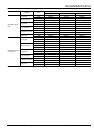
Please select gold-clad contact types
when loads are in the low-level area of
1mA up to 100mA and 5V up to 30V.
For switching of inductive loads (relays,
solenoids, buzzers, etc.), in order to
prevent damage to contacts due to the
occurrence of arcing, an arc absorbing
circuit should be applied
7.Quality check under Actual Loading
Condition
To assure reliability, check the switch
under actual loading conditions.Avoid any
situation that may adversely affect
switching performance.
8.When using lever type switch, care
should be taken not to apply undue
force on the body from the opposite
side or side ways to its operating
direction.
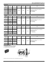
N.C.
side
N.O.
side
Contact
force
Stroke
0
O.T. max.
Usable
area
P.T.
O.T. spedified
value
70% of O.T.
specified value
Ag
Au (-61)
Triple layer contact type
3 A
100 mA
1 mA
0
DC
AC
(Reference only)
5
5
15
30V
30 250V
All Rights Reserved © C
OPYRIGHT Panasonic Electric Works Co., Ltd.