


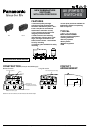
AV3,AVM3/AVT3,AVL3
SPECIFICATIONS
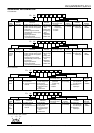
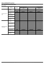
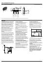
1.Contact rating
Remark: Time constant shall be less than 7 msec. for DC inductive loads.
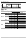
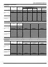
2.Characteristics
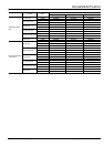
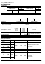
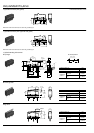
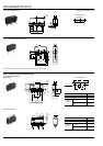
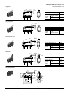
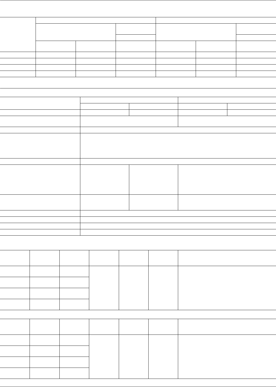
3.Operating characteristics
1) Pin plunger
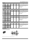
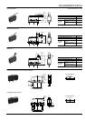
2) Short hinge lever
Voltage
Standard version Long life version
AgNi alloy contact type
Gold-clad contact
type
AgNi alloy contact type
Gold-clad contact
type
Tr iple layer Triple layer
Resistive load
(cos
φ
]1)
Inductive load
(cos
φ
]0.6-0.7)
Resistive load
(cos
φ
]1)
Resistive load
(cos
φ
]1)
Inductive load
(cos
φ
]0.6-0.7)
Resistive load
(cos
φ
]1)
125V AC 3A 2A 0.1A 5A 3A 0.1A
250V AC 3A 2A 0.1A 5A 3A 0.1A
30V DC 3A 2A 0.1A 5A 3A 0.1A
125V DC 0.4A 0.05A — 0.4A 0.05A —
Standard version Long life version
AgNi alloy contact type Gold-clad contact type AgNi alloy contact type Gold-clad contact type
Electrical life at rated load (O.T.max.) 5 × 10
4
at 20 cpm 2 × 10
5
at 20 cpm 5 × 10
4
at 20 cpm 2 × 10
5
at 20 cpm
Mechanical life 5 × 10
5
at 60 cpm (O.T.max.)
3 × 10
7
(O.T.: Specified value)
10
7
(O.T.max.) at 60 cpm
Insulation resistance Min.100MΩ at 500V DC
Dielectric strength
Between non-continuous terminals
Between each terminal and other
exposed metal parts
Between each terminal and ground
1,000 Vrms
1,500 Vrms
1,500 Vrms
Vibration resistance (Pin plunger type) 10 to 55 Hz at single amplitude of 1.5mm (Contact opening: max.1 msec.)
Shock resistance (Pin plunger type)
(Contact opening: less than 1 msec.)
294 m/s
2
min.
(O.F. 0.98 N)
147 m/s
2
min.
(O.F. 0.49 N)
294 m/s
2
min.
(O.F. 0.98 N)
147 m/s
2
min.
(O.F. 0.49 N)
49 m/s
2
min.
(O.F. 0.25 N)
294 m/s
2
min.
Contact resistance (Initial)
50 mΩ max.
(by voltage drop 1 A
6 to 8V DC)
100 mΩ max.
(by voltage drop 0.1 A
6 to 8V DC)
Au: 50 mΩ max. (by voltage drop 0.1 A 6 to 8V DC)
Ag: 50 mΩ max. (by voltage drop 1 A 6 to 8V DC)
Allowable operating speed 0.1 to 1,000 mm/sec.
Max.operating cycle rate 300 cpm
Ambient temeprature –25°C to +85°C (no freezing below 0°C)
Unit weight Approx.2g
4th digit
number of
Part No.
O.F.max. R.F.min. P.T.max. M.D.max. O.T.max. O.P.
0 0.25N 0.020N
0.6mm 0.1mm 0.4mm
Distance from mounting holes: 8.4±0.3mm
Distance from stand-off:
FS 11.8±0.4mm
FS-T 11.7±0.4mm
2 0.49N 0.074N
4 0.98N 0.15N
5 1.47N 0.20N
4th digit
number of
Part No.
O.F.max. R.F.min. P.T.max. M.D.max. O.T.max. O.P.
0 0.098N 0.004N
2.5mm 0.5mm 0.8mm
Distance from mounting holes: 8.8±0.8mm
Distance from stand-off:
FS 12.2±0.9mm
FS-T 12.1±0.9mm
2 0.20N 0.017N
4 0.39N 0.034N
5 0.59N 0.039N
All Rights Reserved © C
OPYRIGHT Panasonic Electric Works Co., Ltd.