10
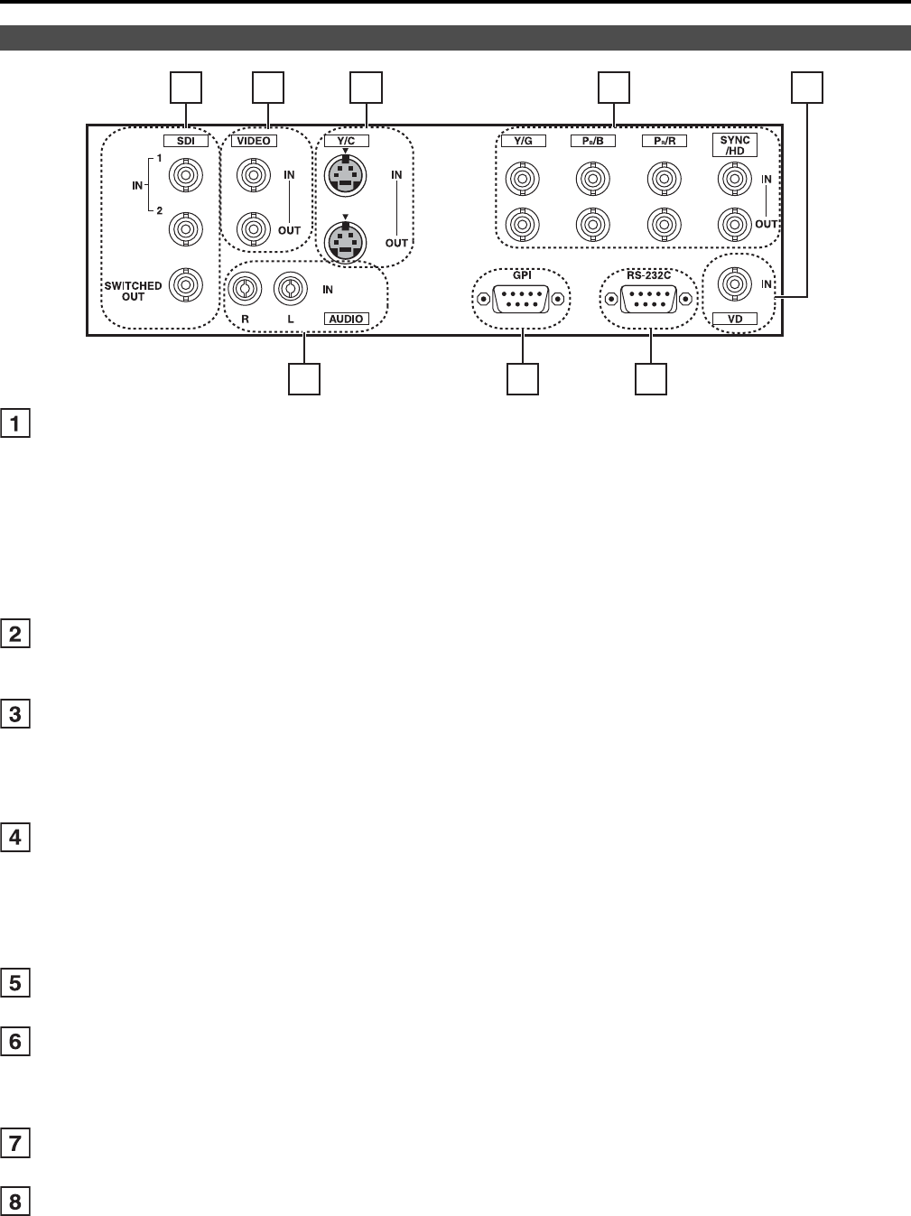
SDI (HD/SD) terminal (BNC)
IN1 : This is the SDI input terminal (compatible with HD/SD automatic switching).
IN2 : This is the SDI input terminal (compatible with HD/SD automatic switching).
SWITCHED OUT
: This is the active through-out terminal for the SDI input signal being displayed on the screen.
* SDI active through-out
Signal output results only when [SDI1] or [SDI2] is selected in [INPUT SELECT]. No output results when the
selected input is not SDI.
The terminal is compatible with embedded audio.
Outputting signals received through the SDI input terminals and converted to analog is not possible.
VIDEO terminal (BNC)
*1*2
IN : This is the VIDEO signal (composite signal) input terminal.
OUT : This is the composite input signal through-out terminal.
Y/C terminal
*1*2
IN : This is the Y/C signal (S-video signal) input terminal.
OUT : This is the Y/C input signal through-out terminal.
* Wide display (16:9) information from the input signal is not automatically detected.
Change the aspect ratio settings, referring to SD ASPECT (J page 19) on the VIDEO CONFIG Menu.
YP
BPR/RGB terminal (BNC)
*1*2
IN : This is the YPBPR/RGB signal input terminal.
OUT : This is the YP
BPR/RGB input signal through-out terminal.
* When using the RGB signal, you can also connect the external synchronizing signal to the SYNC/HD
terminal. When using a PC RGB signal, connect the horizontal synchronizing signal to the SYNC/HD
terminal, and the vertical synchronizing signal to the VD terminal.
VD IN input terminal
This is the vertical synchronizing signal (VD) input terminal used when connecting to a PC RGB signal.
AUDIO input terminal (Pin terminal)
This is the common audio input terminal for all video input terminals.
* When an embedded audio unit BT-YAE1700G (optional) is attached, SDI input audio is automatically
selected by selecting [SDI1] or [SDI2] with [INPUT SELECT].
GPI input terminal (D-SUB 9-pin)
External control is possible by using a GPI signal.
RS-232C input terminal (D-SUB 9-pin)
External control is possible by using a RS-232C signal.
*1 When a cable is not connected to the through-out terminal, the VIDEO IN terminal automatically bears 75 Ω
resistance. When the cable is connected, 75 Ω resistance is removed.
*2 When the through-out terminal is used, depending on connected equipment, the unit's picture level may be
exceeded because 75 Ω resistance at the end of the terminal is automatically removed.
Rear panel
6 78
12 3 4
5
Controls and Their Functions (continued)


