


Multi Function Switches/EVQWH
Design and specifi cations are each subject to change without notice. Ask factory for the current technical specifi cations before purchase and/or use.
Should a safety concern arise regarding this product, please be sure to contact us immediately.
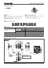
2-φ0.85
+0.05
0
1.6
1.0
3.9
6.1
8.3
5.95
7.95
3.6
2-φ0.8
0
-0.07
3.6±0.05
6-0.3±0.2
0.6
0
-0.07
5.0±0.2
0.4max.
2.05±0.2
C0.2
(0.15)
6.1±0.2
7.1±0.3
2-1.4±0.2
(2.25)
२2.5
0
–0.1
6.5±0.2
7.1±0.3
3.9±0.2
6-0.6±0.2
0.3±0.3
2-0
+0.1
0
1.0±0.3
0.0
+0.1
0
than 0.1mm.
to all terminals have to be less
Distance from mounting surface
Mounting surface
(Height of bent part of cover)
Date code
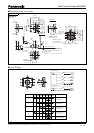
(hole)
Shaft pivot
(Opposite side of
leaning direction)
(Reference)
Prohibited area for
circuit pattern foil
Leaning direction
PWB land pattern for reference
A
B
C
D
E
1
2
3
4
6
5
5432167
7
A
7
7
4
5
1
2
6
3
E
B
C
D
Remark
Direction
Leaning switch and
Center switch
Leaning switch and
Center switch
Leaning switch and
Center switch
Leaning switch and
Center switch
Only Center switch
Leaning switch
Center switch
No. 2
EVQWHA
With boss
■ Dimensions in mm (not to scale)
■ Circuit Diagram
Nov. 2007