


6
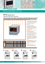
FP-e Series
Technical data
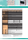
■ General specifications
Item
Rated voltage
Operating voltage range
Allowed momentary power off time
Ambient temperature
Storage temperature
Ambient humidity
Storage humidity
Breakdown voltage
Insulation resistance
Description
24 V DC
21.6 to 26.4 V DC
10 ms
0 to +55°C
–20 to +70°C
30 to 85%RH (non-condensing)
30 to 85%RH (non-condensing)
Vibration resistance
10 to 55 Hz, 1 cycle/min.
Double amplitude: 0.75 mm, 10 min. on X, Y, and Z axes
Shock resistance
Noise resistance
Operating condition
Current consumption
Protection
Mass
98 m/s
2
or more, 4 times on X, Y, and Z axes
1000V (p-p) with pulse widths 50 ns and 1 µs (based on in-house measurements)
Free from corrosive gases and excessive dust
200 mA or less (24 V DC)
IP66-compliant front section (Only when a rubber packing is used.)
Approx. 130 g
Input terminals (COM, X0 to Xn)
Output terminals (Y0 to Y4)
Power supply terminal, Function earth
Input terminal (A0, A1)
COM. (RS232C) terminal
500 V AC for 1 minute
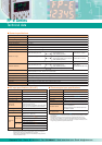
■ DC input specifications (X0 to X7)
Item
Number of input
Insulation method
Rated input voltage
Operating voltage range
Rated input current
Description
8 points (6 points for thermocouple input type)
Optical coupler
24 V DC
21.6 to 26.4 V DC
Approx. 4.3 mA
Input points
per common
8 points/common (6 points/common for
thermocouple input type)
Either the positive or negative of the input power
supply can be connected to common terminal.
ON voltage/ON current
OFF voltage/OFF current
19.2 V or less/4 mA or less
2.4 V or more/1 mA or more
Input impedance
Approx. 5.1 k (X0, X1)
Approx. 5.6 k (X2 to X7)
Response
time
Operating mode indicator
OFF to ON
ON to OFF
50 µs or less (X0, X1)
Note 1)
100 µs or less (X2 to X5)
Note 1)
2 ms or less (X6, X7)
50 µs or less (X0, X1)
Note 1)
100 µs or less (X2 to X5)
Note 1)
2 ms or less (X6, X7)
LCD display (I/O monitor mode)
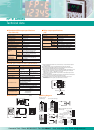
■ Thermocouple input specifications
Item
Number of input
Temperature sensor type
Input range
Accuracy
Resolution
Conversion time
Description
2 points (CH0: WX1, CH1: WX2)
Thermocouple type K
–30.0 to 300.0°C
∗1)
(–22 to 572°F)
±0.5%FS±1.5°C (FS = –30 to 300°C)
0.1°C
250 ms/2CH
∗2)
Insulation method
Between internal circuit and thermocouple input
circuit: noninsulated
∗3)
Between CH0 and CH1 of thermocouple input:
PhotoMOS insulation
Detection function of
wire disconnection
Available
Output terminal (Y5) Power supply terminal, Function earth
Input terminal (COM, X0 to Xn, A0, A1)
COM. (RS232C) terminal
1500 V AC for 1 minute
Input terminals (COM, X0 to Xn) Output terminals (Y0 to Y4) 500 V AC for 1 minute
Input terminals (COM, X0 to Xn) Output terminals (Y0 to Y5)
Input terminals (COM, X0 to Xn)
Output terminals (Y0 to Y5)
Power supply terminal, Function earth
Input terminal (A0, A1)
COM. (RS232C) terminal
Min. 100 M
(measured with 500 V DC)
Note 1) X0 through X5 are inputs for the high-speed counter and have a fast response
time. If used as normal inputs, you should insert a timer in the program as
chattering and noise may be interpreted as an input signal.
Also, the above specifications apply when the rated input voltage is 24V DC
and the tem
p
erature is 25°C.
∗1) Temperature can be measured up to 330°C (626°F). When the measured temperature
exceeds 330°C (626°F) or the thermocouple wiring is disconnected, “K20000” is written
to the register.
∗2) Temperature conversion for thermocouple input is performed every 250 ms. The
conversion data is updated on the internal data register after the scan is completed.
∗3) The internal circuit and thermocouple input circuit are not insulated. Therefore, use the
nongrounding type thermocouples and sheath tubes.
Clearwater Tech - Phone: 800.894.0412 - Fax: 208.368.0415 - Web: www.clrwtr.com - Email: info@clrwtr.com
01/2004