


FP-e Series
Technical data
7
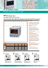
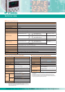
■ Dimensions ■ Wiring diagram
● Input connector
(Standard type)
● Output connector
(Thermocouple input type)
● Power supply/COM. port connector
(RS232C type)
(RS485 type)
24 V DC
COM. port
(RS232C)
Ground
Send data (Output)
Receive data (Input)
Signal Ground
Short
(Terminal station) (Ordinary station)
24 V DC 24 V DC
Ground
COM. port
(RS485)
COM. port
(RS485)
COM
X0
X1
X2
X3
X4
X5
X6
X7
COM
X0
X1
X2
X3
X4
X5
A0+
A0−
A1+
A1−
+
−
Y0
Y1
Y2
Y3
Y4
YC
Y5
COM
TC0
TC1
(+)
COM
Xn
+
−
SD
RD
SG
+
−
E
Ground
+
−
E
L
L
L
L
L
L
Power
Y0 to Y4
(−)
Y5
COM
19200 bit/s 9600 bit/s
■ Transistor NPN output specifications
(For Y0 to Y4)
Item
Insulation method
Output type
Rated load voltage
Operating load voltage range
Max. load current
Max. surge current
Output points per common
OFF state leakage current
ON state voltage drop
Description
Optical coupler
Open collector
5 to 24 V DC
4.75 to 26.4 V DC
0.5 A
1 A
5 points/common
100 µA or less
1.5 V or less
Response
time
50 µs or less (For Y0 and Y1),
1 ms or less (For Y2,Y3 and Y4)
OFF to ON
ON to OFF
50 µs or less (For Y0 and Y1),
1 ms or less (For Y2,Y3 and Y4)
Surge absorber
Operating indicator
Zener diode
LCD display (I/O monitor mode)
21.6 to 26.4 V DCVoltage
6 mA/point (For Y0 and Y1)
3 mA/point (For Y2, Y3, and Y4)
Current
External power
supply (For driving
internal circuit)
■ COM. port communication specifications
∗1)
Item
COM. port type
Description
RS232C
∗2)
RS485
Isolation status with
the internal circuit
Non-isolated Isolated
Transmission distance 15 m 1200 m
Baud rate
∗3)
300, 600, 1200, 2400,
4800, 9600, 19200 bit/s
9600,19200 bit/s
∗4)
Communication method Half-duplex
Synchro system Synchronous communication method
Transmission format
Stop bit: 1 bit/2 bit
Parity: Not available/Available
(Odd number/Even number)
Data length 7 bit/8 bit
Beginning code: STX available/STX not available
Ending code: CR/CR+LF/not available/ETX
Communication mode
• General-purpose
communication
• Computer link
— 99
∗5) ∗6)
Data output order
No. of connected units
Starting from 0 bits per character
■ Relay output specifications
(Y5)
Item
Output type
Rated control capacity
Output points per common
Response time
Life time
Surge absorber
Operating indicator
OFF to ON
ON to OFF
Mechanical
Electrical
Description
Normally open (1 Form A)
2 A 250 V AC, 2 A 30 V DC
1 point/common
Approx. 10 ms
Approx. 8 ms
Min. 2 × 10
7
operations
Min. 10
5
operations (resistive load)
None
LCD display (I/O monitor mode)
∗1) When communicating between FP-e and other devices, it is recommneded to perform
resend processing.
∗2) For RS232C wiring, be sure to use shielded wires for higher noise immunity.
∗3) Set the baud rate of RS485 with the FP-e system register and FP-e internal switch.
Set the baud rate of RS232C with the FP-e system register.
∗4) When sending a command from the FP-e is completed in RS485 communication, send a
response from the receiving device to the FP-e after the following time has elapsed:
9600 bit/s: 2 ms or longer 19200 bit/s: 1 ms or longer
It takes at least 1 scan time (at least 2 ms) for the FP-e to send back a response after
received the command.
∗5) When our C-NET Adapter or RS485 device other than recommended is connected in the
system, the maximum connection number is limited to 32 units.
∗6) For a RS485 converter on the computer side, SI-35 (from LINE EYE Co., Ltd.) is
recommended.
When SI-35 is used in the system, up to 99 units can be connected.
7.5
.
48 70
44.5
(mm)
Internal circuit
Internal circuit
Internal circuit
Clearwater Tech - Phone: 800.894.0412 - Fax: 208.368.0415 - Web: www.clrwtr.com - Email: info@clrwtr.com
01/2004