


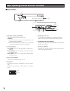
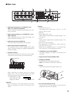
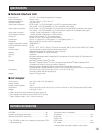
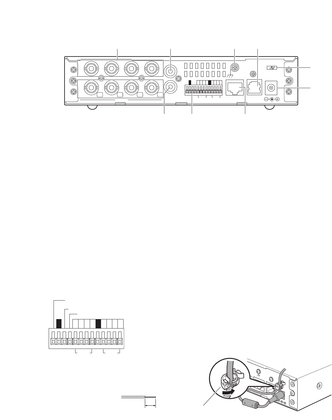
q Video input connectors 1 to 4 (VIDEO IN 1 to 4)
(BNC, 75 Ω, with auto termination)
These connectors accept video input signals from cam-
eras or recorders.
w Video output connectors 1 to 4 (VIDEO OUT 1 to 4)
(BNC, loop-thru)
These connectors loop thru video input signals sup-
plied to VIDEO IN connectors 1 to 4.
e Audio input connector (AUDIO IN)
RCA audio cable is connected to this connector.
r Audio output connector (AUDIO OUT)
This connector (RCA pin jack) supplies audio output
signal. Connect the cables to a speaker equipped with
the audio amplifier.
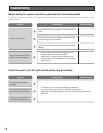
t Connector terminal
These are the connectors for alarm input, alarm output,
AUX (auxiliary control) output, and time adjust input.
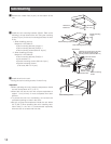
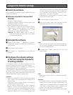
When connecting an external device, first remove
approx. 9 mm - 10 mm of the outer jacket of the cable
and twist the cable core to prevent a short circuit.
• Specification of cable
(wire): AWG #22 - #28,
Single core, twisted
Important:
• Do not connect 2 or more wires directly to a terminal.
When it is necessary to connect 2 or more wires, use a
splitter.
<Ratings>
• Alarm input (IN 1 to 4):
Non-voltage make contact input, –100 mA, +5 V DC
pull-up, 100 ms or more
• GND (G)
• Alarm output (OUT 1 to 4):
Open collector output Maximum applied voltage: +24 V
DC, 100 mA
• AUX 1:
Open collector output Maximum applied voltage: +24 V
DC, 100 mA
• NC: Do not connect anything.
• Time adjust input: +5 V DC pull-up, –100 mA make con-
tact input, 100 ms or more
• Signal input is accepted by up to ± 15 seconds every
hour on the hour. Time is adjusted on the hour.
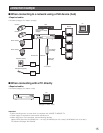
y 10/100 Base-T port (10/100 BASE·T)
LAN cable (Category 5 or better) is connected to this
connector.
u Signal Ground Terminal (SIGNAL GND)
i RS-485 port (RS-485)
RS-485 devices are connected to this port.
Note: This connector is reserved for future use.
o Clamp
Fastens the supplied AC adapter’s power cord.
!0 DC 12 V Input Jack (DC 12V IN)
Connect to a DC 12 V power supply. Do not use any AC
adapter other than the one supplied.
13
■ Rear view
IN
4
4
OUT
IN
OUT
VIDEO
AUDIO
ALARM
10/100BASE•T
RS-485
DC12V IN
3
3
2
2
1
1
4321 4321GG
OUT IN
SIGNAL
GND
qw ui
o
!0
ytr
4321 4321GG
Input
Time adjust input
NC
AUX 1
Output
Approx. 9 mm - 10 mm
10/100BASE•T
RS-485
DC12V IN
1
SIGNAL
GND
Clamp