


4
3000-A2-GZ41-50
July 1999
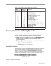
Table 1. Rear Connector and V.35 Adapter Pin Assignments
25-Pin Connector
on Rear
Connector Plate
34-Pin
Connector on
V.35 Adapter
Circuit Name
7
4
5
6
8
20
21
18
19
24, 11
23, 22
15, 2
16, 3
14, 1
9
10
25
B
C
D
E
F
H
J
L
N
P, S
R, T
U, W
V, X
Y, AA
HH
KK
NN
Signal Ground
Request-to-Send (RTS)
Clear-to-Send (CTS)
Data Set Ready (DSR)
Received Line Signal Detect (RLSD)
Data Terminal Ready (DTR)
Ring Indicator (RI)*
Local Loopback (LL)
Remote Digital Loopback (RL)
Transmitted Data (TXD)
Received Data (RXD)
Transmitter Signal Element Timing – DTE Source
Receiver Signal Element Timing – DCE Source
Transmitter Signal Element Timing – DCE Source
Positive dc Test Voltage
Negative dc Test Voltage
Test Mode (TM)
* Ring Indicator is available only on a DMB-S or a DBM-V.
Warranty, Sales, Service, and Training Information
Contact your local sales representative, service representative, or distributor
directly for any help needed. For additional information concerning warranty,
sales, service, repair, installation, documentation, training, distributor locations, or
Paradyne worldwide office locations, use one of the following methods:
H Internet:
Visit the Paradyne World Wide Web site at www.paradyne.com.
(Be sure to register your warranty there. Select
Technical Support
→
Warranty Registration.
)
H Telephone:
Call our automated system to receive current information by fax
or to speak with a company representative.
— Within the U.S.A., call 1-800-870-2221
— Outside the U.S.A., call 1-727-530-2340
Document Feedback
We welcome your comments and suggestions about this document. Please mail
them to Technical Publications, Paradyne Corporation, 8545 126th Ave. N.,
Largo, FL 33773, or send e-mail to userdoc@paradyne.com. Include the
number and title of this document in your correspondence. Please include your
name and phone number if you are willing to provide additional clarification.
*3000-A2-GZ41-50*
*3000–A2–GZ41–50*
Copyright E 1999 Paradyne Corporation