9
Connecting the Model 3550 DSU’s Port 2
For the EIA-232 cable, install as described above.
For the V.35 cable, install the V.35 adapter, then the V.35 DTE cable as follows.
" Procedure
1. Reconfigure the port for a V.35 interface. See
General Configuration Options
on
page 21.
2. Connect the 25-pin plug end of the V.35 adapter (Feature Number 3000-F1-510) to
Port 2. Tighten the thumbscrews.
3. Connect the plug end of the 34-pin V.35 DTE cable to the other end of the V.35
adapter. Tighten the holding screws.
4. Connect the other end of the DTE cable to the appropriate port on the computer or
DTE. Tighten the holding screws.
Changing the Model 3551 DSU Hardware Straps
The Model 3551 DSU has several hardware straps that control the permissive or
programmable connection when a DBM is installed, the Test Mode Indication leads, and
the external interface leads (used with a –48 Vdc Central Office Power Unit).
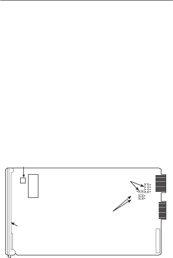
Refer to the following figure to locate the switch and jumper locations. If a DBM is
installed, refer to Table 2 to determine which switch needs to be changed, if any. Refer
to Table 3 to determine whether these jumper straps need to be changed.
P7
Faceplate
99-16245
Test Mode
Indication Jumpers
(Shown Enabled)
J13
J12
RearTop
J21
–48 Vdc Alarm
Monitoring
(Shown Disabled)
J20
Switch 1


