


14
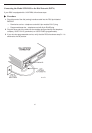
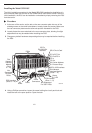
7. At the rear of the carrier, connect the appropriate DTE interface cable (EIA-232-D
or V.35) to the rear connector plate. For an EIA-232-D interface cable, connect the
EIA-232-D cable to the top DTE connector on the rear connector plate.
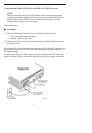
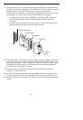
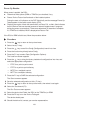
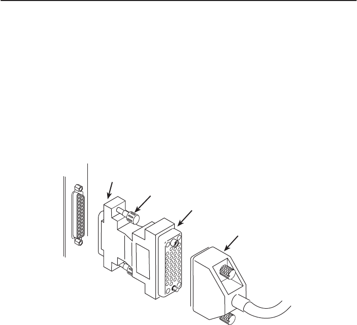
For the 25-pin V.35 interface, a V.35 adapter is shipped with the unit. To connect a
V.35 adapter to the 25-pin V.35 connector, perform the following steps:
— Connect the 25-pin end of the V.35 adapter to the bottom DTE connector of
the rear connector plate. Tighten the thumbscrews on each side of the
connector.
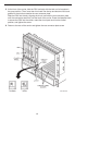
— Connect the V.35 interface cable to the 34-pin end of the V.35 adapter, then
tighten the screws on each side of the cable connector.
25-Pin Connector
V.35 Adapter
V.35 Cable
Thumbscrews
99-16298
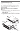
8. The installed DSU is connected to the DDS network through the 50-pin connectors
at the rear of the carrier. These interfaces are specified in the USOC RJ48T, and
the pin assignments are shown in Appendix D of the User’s Guide. Proper network
connection to the DDS facility or to the network channel-terminating equipment
must be made at the far end of the cable.
9. If the network line and remote DSU are installed and tested, do a Remote
Loopback – a Test Pattern test.
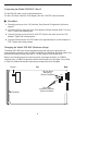
10. If the Front Panel test switch strap is to be disabled, slide the DSU slightly out of
the carrier, open Switch S3-1, then reseat the DSU into the carrier.
Do this now
.
11. Circuit ID information can be written on the cover plate under the appropriate slot
number.