COMSPHERE –48 Vdc Central Office Power Unit
iv May 1998 3000-A2-GB41-40
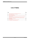
List of Tables
Table Page
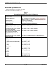
1-1 Technical Specifications for Central Office (CO) Power Unit 1-4. . . . . . . . . . . . . . . . .
2-1 Maximum Ambient Temperatures Permitted 2-2. . . . . . . . . . . . . . . . . . . . . . . . . . . . . . .
2-2 Settings for Basic Mode 2-6. . . . . . . . . . . . . . . . . . . . . . . . . . . . . . . . . . . . . . . . . . . . . . .
2-3 Settings for Independent Mode 2-7. . . . . . . . . . . . . . . . . . . . . . . . . . . . . . . . . . . . . . . . .
2-4 Settings for Redundant Mode Using a Single –48 Vdc Power Source and a Single
Input Power Cable 2-7. . . . . . . . . . . . . . . . . . . . . . . . . . . . . . . . . . . . . . . . . . . . . . . . . . .
2-5 Settings for Redundant Mode with Either a Single Power Source and Two Input
Power Cables, or Two Separate Power Sources and Two Input Power Cables 2-7. . . . .
2-6 Jumper Settings 2-17. . . . . . . . . . . . . . . . . . . . . . . . . . . . . . . . . . . . . . . . . . . . . . . . . . . . .
A-1 Pin Assignments of the DC Inputs A-2. . . . . . . . . . . . . . . . . . . . . . . . . . . . . . . . . . . . . . .
A-2 AMP Part Numbers A-3. . . . . . . . . . . . . . . . . . . . . . . . . . . . . . . . . . . . . . . . . . . . . . . . . .
A-3 Pin Assignments for the CO Alarm System Outputs A-4. . . . . . . . . . . . . . . . . . . . . . . . .
A-4 Pin Assignments for the NMS Adapter Cable A-5. . . . . . . . . . . . . . . . . . . . . . . . . . . . . .


